background image

48

TRANSLATION OF THE ORIGINAL INSTRUCTIONS (Keep for future reference)

Document Code 

Rev. 

Date saved 

Date printed

U400 INSTRUCTIONS 

01 

02/10/2015 

02/10/2015

EN

5.10. LUBRICATION

During lubrication operations:
1.  Avoid bringing oil and/or grease into contact with the skin.
2.  During oil and/or grease changes use protective gloves.

–%?"&%#&<?*'$#&%#??*\"**%&+<"#**'$#&%$&*%\*'$#&%<#*$&%#$%#"$$%;$
waste disposal company.

All lubrication operations must be performed:
 #%%$%%&#**;%&#*&\""*[
2.  strictly observing the safety indications given in the “safety datasheets” provided with each individual lubrication product used.

The lubrication operations which must be performed by maintenance technicians are indicated below.

To obtain high performance and faultless operation, it is important to lubricate moving parts of the machine on a regular basis.

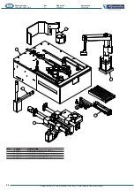
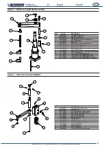
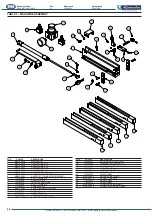
The position of machine components which need lubricating is shown in the layout provided as an appendix to this manual.

For the disposal of spent oil and grease, observe the relative legislation in force.

&%<""&%*&%?&@&!&%&&%%"$$#**\#%?<$**$%&$&%

 NOTES


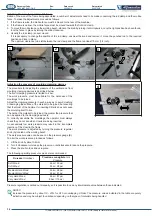
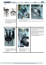
Fixed guards must be removed in order to gain access to some of the parts requiring lubrication. 


&$*'$#%&"#%&?#@'&$!"*%<[#**%?;<#<!%'%%<#&<$<&"*#$

Cont...

Summary of Contents for Alfamacchine U400

Page 1: ...EASE RETAIN FOR FUTURE REFERENCE Name Function Model Type Serial number Year of manufacture Manual Revision FRAME ASSEMBLING MACHINE ASSEMBLY OF FRAMES BY INSERTION OF METAL V NAILS U400 previous vers...

Page 2: ...me FRAME ASSEMBLING MACHINE Funzione Purpose ASSEMBLY OF WOODEN AND SYNTHETIC MDF MOULDINGS USING METAL V NAILS Modello Model Name U400 Tipo Type PNEUMATIC Numero di Serie Serial Number E CONFORME ALL...

Page 3: ...INE 19 3 3 ASSEMBLY OF SEPARATELY SHIPPED UNITS 20 4 INITIAL START UP AND USE OF THE MACHINE 25 4 1 WORKSTATIONS AND OPERATORS TASKS 26 4 3 CHECKS ADJUSTMENTS AND START UP 26 4 4 START UP 27 4 5 WORKI...

Page 4: ...DATIONS PROVIDED IN THIS MANUAL NEVER TAMPER WITH IT FORCE IT OR USE IT INANYINAPPROPRIATE MANNER 1 INTRODUCTION TO USE 1 1 HOW TO CONSULT THIS MANUAL AND THE SYMBOLS ADOPTED Please pay particular att...

Page 5: ...d improper and therefore strictly prohibited the dimensions specified in the heading TECHNICAL CHARACTERISTICS It is also compulsory received adequate training information concerning machine operation...

Page 6: ...ndstill j as indicated in this manual outdoors or worksites with open windows and doors processing of materials and products that are not expressly indicated in the present manual processing of metal...

Page 7: ...of at least IP54 0 C 32 F with electrical equipment protection rating lower than IP54 Ambient working temperature 5 C 41 F T 45 C 113 F Transport and storage temperature between 25 C 13 F andd 55 C 13...

Page 8: ...j 1 4 TECHNICAL FEATURES Machine characteristics Work surface dimensions W x L 400x600mm 16 x24 Machine length 600mm 24 Machine width 640mm 25 870mm 34 1 4 1020mm 40 Machine height 1330mm 53 Maximum...

Page 9: ...ngs of various hardness with multiple surface The main technical characteristics of the products handled by the machine described herein are provided below DESCRIPTION OF PRODUCTS HANDLED CHARACTERIST...

Page 10: ...due to the combustibility of the substances used in the machine and the products handled by the same To avoid the hazards resulting from the employer in addition to training and adequately informing t...

Page 11: ...the instructions provided in this manual must never place What s more workers must never wear rings wrist watches personal accessories that may constitute a risk Make sure sleeves 1 9 DESCRIPTION OF S...

Page 12: ...by authorized maintenance technicians maintenance technicians Irrespective of the circumstances dangerous openings in the machine safeguards they will not remain lodged in their locations in the abse...

Page 13: ...e controlled manually by the operator who directly activates the pneumatic actuators complete with lever with manually activated button mouldings clamping system mobile fence and pedal If purchased wi...

Page 14: ...lting in incomplete insertion of the V nail and a j The unit is made up of a mechanical or magnetic stopper holder to which the interchangeable rubber stoppers P of varying hardness are applied locate...

Page 15: ...the V nails against the guide each time the hammer is activated The hammer is activated by a manually operated pneumatic cylinder Perfect mechanical alignment of these parts ensures precise insertion...

Page 16: ...ng fence unit with a 90 angle for frames with 4 sides installed as standard equipment is made up of the following main elements C Knob for locking the fence unit D Fixed fence with 90 corner interchan...

Page 17: ...it on the opposite side For further details see the heading ADJUSTMENTS A Locking handle for the upper travel stop B Locking handle for the bottom travel stop C Metric imperial ruler D Double command...

Page 18: ...at a temperature of 20 C 68 F 5 9 m s2 0 6G or higher 900 mbar or more Avoid places where there may be unexpected changes in temperature which could lead to the formation of condensate or freezing St...

Page 19: ...ER CAUTION g to the intended installation site as possible Said site must be checked beforehand to obtain information about the necessary clearances and dimensions Q procedures g The forks on the equi...

Page 20: ...icated on the packaging falls within the maximum hoisting capacity of the chosen lifting equipment DANGER CAUTION Do not rig the machine up with belts for handling operations When storing the machine...

Page 21: ...ress during normal use of the machine and undue strain to the structure the machine must be stabilised during lifting operations The standard machine is supplied ready assembled on the stand which is...

Page 22: ...hese activities are therefore the sole responsibility of the machine manufacture s personnel _ The working bench extensions are optional and may be requested from the manufacturer Their installation r...

Page 23: ...support surface when the double stopper presses down on the ends of the mouldings An example of how to install the brackets is provided below To install the extensions proceed as follows 1 Check that...

Page 24: ...w simple steps as described below 1 Screw the four support feet into the base of the stand 3 Join the base to the uprights using the 4 screws provided 4 Add the cradle by inserting the supports on the...

Page 25: ...ode Rev Date saved Date printed U400 INSTRUCTIONS 01 02 10 2015 02 10 2015 EN j optional can be installed j 2 Screw in the connector for the compressed air line 3 Secure the unit in place with the 2 s...

Page 26: ...h the machine s pneumatic circuit in compliance with legislation and the legislative and regulatory provisions in force in the country of installation j protected operation of the machine The followin...

Page 27: ...ed air isolation device as can be seen in the pneumatic diagram supplied with the machine is supplied for the sole source normal conditions of use PNEUMATIC SUPPLY ISOLATOR DEVICE The unit is located...

Page 28: ...ng operations while the machine is running In the event of a problem he she must not intervene but simply call the Maintenance Service All operations performed by the operator must be carried out with...

Page 29: ...alve 1 lever to the OFF position B the V nail pusher cylinder is opened C Insert the stick of V nails in the magazine 2 ensuring that the sharp part glued edge is facing upwards and that the V is posi...

Page 30: ...the V nail pusher 3 Press the red button to move the carriage beyond the upper travel stop 5 Keeping it at a slight tilt insert the new loader in the magazine then press down 2 If necessary to get ov...

Page 31: ...tion move the L block support up against the hammer and tighten the socket head screws 5 Move the magazine up against the L block support after having loosened the two M5 screws locking the magazine i...

Page 32: ...e that the centre of the head is aligned with the line of the fence 2 Another method for aligning the fences is obtained using a reference frame with a very precise cut at 90 120 or 135 depending on t...

Page 33: ...be used to NOTE the declared stroke of the machine 200 mm is determined based on the use of the standard 90 fence If fences with other angles are used 120 135 the stroke is reduced due to the additio...

Page 34: ...r C Magnetic stopper holder D Magnetic support E Round magnetic felt stopper 2 To replace the stopper holder B C or D you must unscrew the screw H which secures it to the rod and pull it downwards and...

Page 35: ...ired hardness in the stopper holder positioning it under the slot and manually pressing it in place To remove the stopper A simply pull it out with your hand by gently taking hold of one of the two si...

Page 36: ...V Nails does not cause the moulding itself to rise can be applied to the clamping devices is To correctly assemble the mouldings the operator must always check they do not rise when V nails are being...

Page 37: ...the working bench to the required position 3 Re tighten the handle once the required position has been achieved located under the machine caused by the tilt would be much heavier to move To calibrate...

Page 38: ...SUGGESTIONS FOR MAKING PERFECT JOINS 1 V nail types j using a wide variety of materials different V nails are available with different degrees of sharpness suitable for use with different hardness va...

Page 39: ...ed by the button 5 Position the handle on the other side 6 Secure the handle to the carriage with the 2 screws and reconnect the three pipes in the exact same position as they were before 1 Remove the...

Page 40: ...served during machine operation Insert the compressed air supply line directly into the machine or against the right stop on the fence and then position the left one pneumatic pedal to activate the fr...

Page 41: ...aults 4 limit the number and duration of interventions 5 2 WORK STATIONS AND MAINTENANCE TECHNICIAN DUTIES The maintenance technician duties are troubleshooting and the replacements of worn or damaged...

Page 42: ...HAVE BEEN REPLACED 5 5 ISOLATION FROM EXTERNAL ENERGY SOURCES During maintenance cleaning and replacement of parts the machine must not be used and no commands must be transmitted Before performing a...

Page 43: ...provide equivalent quality and safety Check their integrity both internally and externally and make sure there are no signs of wear or breakage For any type of intervention or to replace parts call in...

Page 44: ...V nails inserted CHECK Check replace 1 Slacken the locking handle on the stand to tilt the working bench backwards Disconnect the air supply from the machine 2 Disconnect the 2 pipes connected to the...

Page 45: ...sert it in the special hole taking care not to pinch the lip seal 9 Note position the hammer so that the high part of the piston has the two raised edges pointing towards the magazine 10 Replace the c...

Page 46: ...oisture to keep said areas of the machine in a suitable operating condition Use suitable tools and equipment to check the tightness of terminals screws nuts bolts and connections in general on both th...

Page 47: ...simple personal protective equipment Cleaning operations of the internal parts of the machine must be performed by the maintenance service operations should be carried out by the same personnel who u...

Page 48: ...type of operation being carried out and depending on the substances used for cleaning Comply with the methods of use and use all the necessary PERSONAL PROTECTIVE EQUIPMENT SPECIFIED BY THE SUPPLIER O...

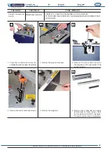
Page 49: ...OADERS TO PERFORM THIS OPERATION THE MAGAZINE MUST BE DISMANTLED AS FOLLOWS 1 Press the red button and move the carriage beyond the upper travel stop 2 Remove the plug from the seat 3 Remove the screw...

Page 50: ...cations given in the safety datasheets provided with each individual lubrication product used The lubrication operations which must be performed by maintenance technicians are indicated below To obtai...

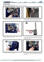
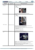
Page 51: ...ng ROUTINE MAINTENANCE Lubricate the carriage guides located under the working bench To gain access and perform lubrication the maintenance technician must 1 Isolate the machine from external power su...

Page 52: ...ressed and then the button is pressed the properly more than once operation starts out correctly but j Insufficient operating pressure V nails badly positioned in the loader V nail guide channel L blo...

Page 53: ...ves around during V nail insertion Worn hammer Obstructed hammer not at the same level as the working bench Check that the AFC braking system is working properly Balancing cylinder powered Machine mov...

Page 54: ...RENDERED INOPERATIVE AND FREE FROM ALL POTENTIAL HAZARDS Decommissioning of the machine must be carried out by specialised and suitably equipped personnel If the client does not have the right personn...

Page 55: ...all plastics metal materials and electrical components which must be disposed of separately are duly sorted The employer must be aware of all the statutory legislation in force in the country of dispo...

Page 56: ...t Code Rev Date saved Date printed U400 INSTRUCTIONS 01 02 10 2015 02 10 2015 EN POS CODICE DESCRIZIONE 1 TAVOLA 1 MONTAGGIO PIANO DI LAVORO 2 TAVOLA 2 MONTAGGIO SLITTA 3 TAVOLA 3 MONTAGGIO BLOCCAGGIO...

Page 57: ...0012 BLOCCAGGIO ORIZZONTALE U400 10 240450044 SERBATOIO 11 735630004 MICROREGOLATORE 0 4 1 8 12 365010130 TAPPO NYLON D 13 13 M29100011 ARRESTO 14 M29000015 ASTA FOGLIA 15 365210335 TARGHETTA CRUSCOTT...

Page 58: ...04 COMPLESSIVO FRENO 11 M30000009 SUPPORTO CILINDRO ARRESTO 12 753750017 CILINDRO ARRESTO 13 M30100002 BLOCCHETTO ANTERIORE ASTE 14 M30100003 SPESSORE BLOCCHETTO 15 M30100005 BLOCCHETTO POSTERIORE AST...

Page 59: ...M12x25 12 242230300 SUPPORTO PORTA TAMPONE ANGOLARE 13 710100067 VITE TCEI M6x140 14 397100005 PORTA TAMPONE MAGNETICO 397100001 TAMPONE INTERCAMBIABILE NERO 397100002 TAMPONE INTERCAMBIABILE GIALLO 3...

Page 60: ...10 718100002 RONDELLA M5 11 753320014 TESTA A SNODO RF4 12 710100006 VITE TCEI M4x16 13 718100001 RONDELLA M4 14 M30100065 PERNO MOVIMENTAZIONE 15 715650002 DADO M5 16 753320013 PRESSORE M5 17 710100...

Page 61: ...00042 GRANO M12x1 25x16 3 336100060 RONDELLA CON RIPRESA 4 753170014 MANIGLIA M8x25 5 710100115 VITE TCEI M8x25 6 710100122 VITE TCEI M8x70 7 M29000007 BASE CAVALLETTO 8 M29000006 CULLA CAVALLETTO 9 7...

Page 62: ...011 SPINA D4x20 3 753170009 MANIGLIA M8x25 4 730160002 RACCORDO M5 TUBO 5 714300008 GRANO M5x5 6 M30100087 PERNO PROTEZIONE 7 710100117 VITE TCEI M8x35 8 714300073 GRANO M5X8 9 710100203 VITE TCEI M3x...

Page 63: ...0 UHDWHG E 1 52 63 1 3817 0 5 2 725 8662 5 2 725 35 66 21 9 92 3 9 0 12 1 52 0 57 772 9 92 0 57 772 6 1 725 9 92 2 2 5217 9 92 2 2 9 57 1 52 2 2 9 57 0 1 52 2 2 25 217 0 5 2 725 35 66 21 2 9 92 3527 2...

Page 64: ...ALFAMACCHINE S r l Via Selva 23 25 47122 Forl FC Tel 39 0543 783301 Fax 39 0543 783302 http www alfamacchine com...

Reviews: