Maintenance, Adjustments,
Troubleshooting and FAQ
24
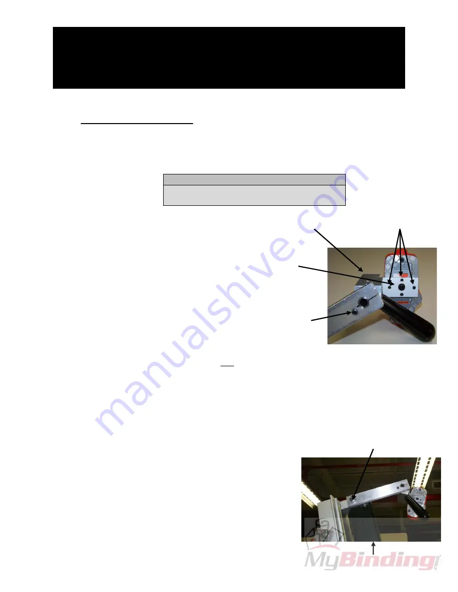
M10 x 35mm Bolt attaching
the Laser Assembly to the
Vertical Track
Assembly
Vertical
Track
Assembly
IV.
Installing the Laser
37.
Setting Up the Laser
Tools Needed:
Tools
Needed
10mm,
16mm,
17mm
Wrenches
2mm,
2.5mm,
4mm
1/8"
Hex
Keys
1. Loosen the black Handle by turning
it counterclockwise.
2. Slide the Laser all the way to the
left along the Laser Shaft.
3. Ensure the brass-tipped Set Screw
on the Laser Assembly is tight
against the Laser Mount, and
retighten the Handle.
4. Hold the Laser in the palm of your
hand so the four (4) black Set
Screws on the left side of the Laser
are facing you.
5. Loosen the four (4) Set Screws
using a 2mm Hex Key.
6. Tighten the center, mounting Screw using a 1/8" Hex Key.
7.
Retighten the four (4) Set Screws
just
until they come in contact with the Laser
.
♦
Note: Do not over tighten the Set Screws. You will be making some fine
adjustments to the Set Screws during calibration.
38.
Mounting the Laser to the FSC
♦
Notes:
•
You will need a stepladder to complete this task.
•
Depending on your FSC model, there may already
be a Bolt in the Laser Assembly Mounting Hole.
Remove it using a 17mm Wrench.
1.
Attach the Laser Assembly to the top, left-hand side of the
Vertical Track Assembly
(see Figure to the right).
2.
Insert and tighten the M10 x 35mm bolt supplied with the
Laser using a 17mm Wrench.
Center Mounting
Screw
Four Set Screws
Brass-Tipped
Set Screw
Laser Mount


