Maintenance, Adjustments,
Troubleshooting and FAQ
26
5.
Place the Cutting Head at the top of the substrate and make a cut approximately 1" (2.5 mm)
in length.
6.
Remove the Aluminum Composite Wheel and return the Cutting Head to its resting position
at the bottom Vertical Track Assembly.
41.
Calibrating the Laser to Cut Lines
CAUTION: Use Laser Safety Goggles before turning on the Laser.
A. Creating a Continuous Laser Beam
1.
Turn on the Laser. The switch is located on the right side
of the Laser. Slide the On/Off switch down to the On
position.
2.
If Laser Beam is visible from the top of the substrate to
the bottom, skip to “Setting the Angle of the Laser
Beam,” Section 41.-B. on page 26.
3.
If the Laser Beam is not entirely visible from the top of
the substrate to the bottom:
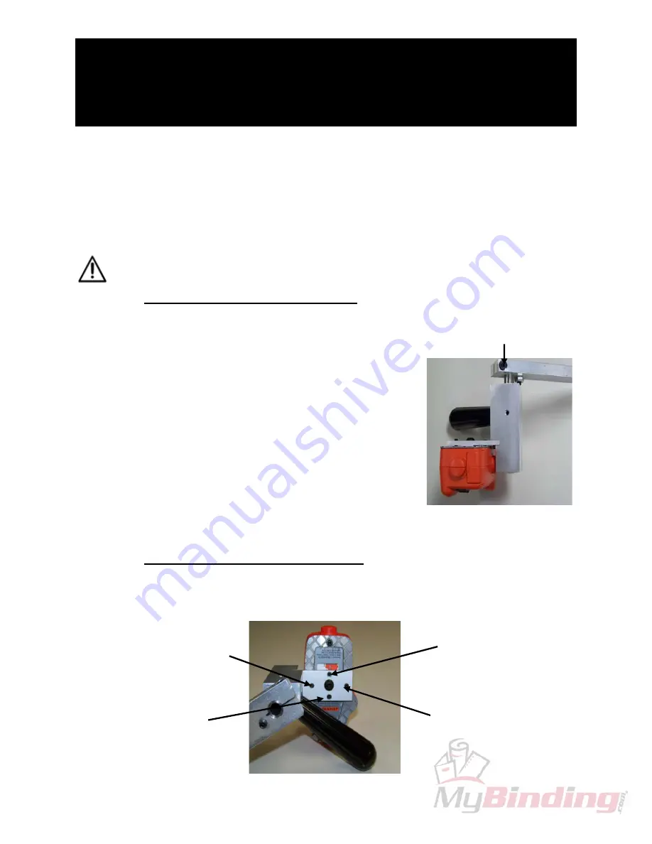
a. Use a 4mm Hex Key, to loosen the Laser Shaft
Clamping Screw located on the top of the Laser
Shaft
(see Figure on the right).
b. Rotate the Laser using the Handle until the beam
becomes continuous from the top to the bottom of
the substrate.
c. Retighten the Laser Shaft Clamping Screw.
B.
Setting the Angle of the Laser Beam
Follow the steps below to create a beam that fall directly on top of your score line. Once
your score line is perfectly matched up with the Laser Beam, you are finished.
Top Set Screw
moves beam left
Back Set Screw
(farthest from you)
moves beam clockwise
Laser
Shaft
Clamping
Screw
Bottom
Set
Screw
moves
beam
right
Front
Set
Screw
(closest
to
you)
moves
beam
counterclockwise


