background image

Operation 


1


I.


OPERATING THE GEMINI PRO 

1.


Unpacking Materials  

Check the exterior of the packing box to make sure there is no visible damage.  After unpacking 
the unit, check


to make sure you have all the parts and there is no damage to the machine.  Lay 

out drill for attaching wall brackets, if you did not purchase the Atlas Workbench. 

A. 

Gemini Pro Components 


Rail with Cutting Head already assembled 


Shelf brackets to hang machine when not in use (not used with Atlas Workbench).  The 
number of brackets corresponds to the size of the cutter. 

9

  Two (2) brackets for Gemini Pro 40", 60" or 80" (1m, 1.5m or 2.0m) 

9

  Three (3) brackets for Gemini Pro 100" or 120" (2.0m and 3m) 


One (1) Cutting Blade Magazine with Blade Stiffener 


One (1) Box of 100 Blades 


One (1) Sight-Line Guide Strip 


Hex Key Wrenches (2mm & 2.5mm)  

2.


Installing the Sight-Line Guide Strip 

1. 

Position the Gemini Pro upside down with both ends raised to keep the Cutting Head 
suspended above the work surface. 

2. 

Ensure the cutting edge of the unit is in front of you. 

¾

Tip:   Use two (2) boxes approximately the same size to support the cutter. 


CAUTION: Do not place the cutter directly on its Cutting Head or damage may occur. 
 

3. 

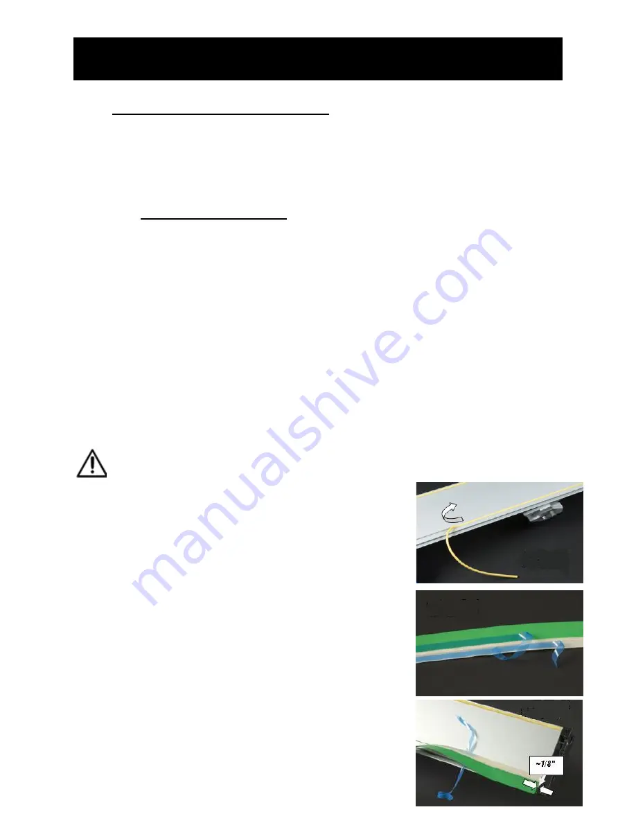
Locate the yellow rubber strip in the slot that is closest 
to the cutting edge on the unit. 

(Figure 1)


4. 

Carefully remove it.  

5. 

Using a clean cloth and 50-70% isopropyl alcohol 
(rubbing alcohol), clean any dirt or debris from either 
side of the newly created slot. 

 Note:  Let the alcohol dry completely before 

continuing to the next step. 

6. 

Locate the green Sight-Line Guide Strip from the 
unpacked materials. 

7. 

Position the Guide Strip so the green portion is above 
the cream-colored portion. 

8. 

Peel back approximately 6" (155mm) from the right 
side of both of the blue adhesive liners. 

(Figure 2)  

9. 

Turn over the Guide Strip and position the rib of the 
Guide Strip over the slot. 

 Note: The green plastic strip is toward the 

cutting edge.


10. 

Start the Guide Strip approximately 1/8" (4mm) in 
from the right black End Cap. 

(Figure 3)


Figure


1


Figure


1

Figure


2


Figure


3

Summary of Contents for Gemini Pro 100

Page 1: ...Fletcher Terry Gemini Pro 100 Rail Cutter Instruction Manual...

Page 2: ...ny 65 Spring Lane Farmington CT USA 06032 3311 Tel 860 677 7331 Toll Free 888 888 5165 Fax 860 676 8858 customerservice fletcher terry com www fletcher terry com OWNER S MANUAL Fletcher Gemini Pro Gem...

Page 3: ...rnative Installation 2 C Mounting the Shelf Brackets for Storage 2 3 Installing the Blade 3 4 Inserting the Blade Magazine 3 5 Cutting Various Materials 3 A Cutting Flexible Materials 3 B Cutting Boar...

Page 4: ...ny questions you can find more information at Fletcher s website at www fletcher terry com or contact our Customer Service Department toll free at 800 843 3826 in the United States Outside the United...

Page 5: ...Gemini Pro is for cutting and trimming Gatorboard foamboard PVC corrugated plastic polystyrene and any other scissorable materials It must not be modified or used for any other application or purpose...

Page 6: ...tting Head suspended above the work surface 2 Ensure the cutting edge of the unit is in front of you Tip Use two 2 boxes approximately the same size to support the cutter CAUTION Do not place the cutt...

Page 7: ...Cutting Head to the far left 23 Make another cut just until the new cut meets the original cut 24 Move the Cutting Head to the middle of the cutter 25 Using a utility knife continue the cut made by th...

Page 8: ...ng the Blade Magazine 1 Loosen the black Blade Locking Knob located on the front of the Cutting Head 2 Hold the Magazine so the Blade Stiffener is facing you and the blade is to the left 3 From the ri...

Page 9: ...th the Guide Strip 2 Position the Cutting Head to its farthest left position 3 Place your left hand on top of the Cutting Head and rotate the Cutting Head down so the Blade is depressed 4 Push the Cut...

Page 10: ...nd they might develop a slight amount of movement side to side Tighten the Head Adjustment Screws in order to eliminate this To avoid over tightening slide the Cutting Head slowly while tightening to...

Page 11: ...100 2 5m and 120 3m Q What is the maximum material thickness A The maximum thickness is 13mm 10 Replacement Parts List To order Replacement Parts contact Fletcher Terry s Customer Service Department...

Page 12: ...Bumper Bearings Replacement Kit for Cutting Head assembly 17 560 Gemini Pro Sight Line Guide Strip Kit 40 17 810 Gemini Pro Sight Line Guide Strip Kit 60 17 811 Gemini Pro Sight Line Guide Strip Kit 8...

Reviews: