Reference Board BMR 481 P1E+
287 01-ROA 170 014 Rev A 2018-10-16
6 (12)
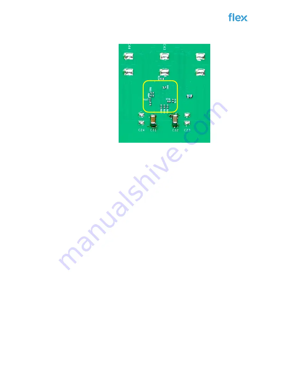
Figure 1b. ROA 170 014 (bottom side).
Position Description (Top Side)
1
Input voltage connectors.
2
Output voltage connectors.
3
Power Good LED.
4
Enable switch on LED.
5
ENABLE switch.
6
Connector for the PMBus-to-USB adaptor (KEP 910 17).
7
SMB Oscilloscope connectors for Vin and Vout, See Sec 7.
8
Connector for driver, controller and auxiliary supplies.
9
Space for additional output capacitors.
10
Positions for populating Flex electronic load, PuLS.
11
VCTRL power on LED.
12
Vin power on LED.
13
Fault detected and SALERT LED.
14
Space for additional input capacitors.
15
Supply option jumpers.
16
Sense location jumpers.
17
MAIN and SATELLITE modules.
18
PWM probing points.
19
Phase Active LEDs. See Sec 6.
Position Description (Bottom Side)
20
Resistors for termination of current sense
– 0 Ohm resistor
shall be mounted for un-populated SATELLITE positions.
See Sec 9 for details.
20


