


—5—
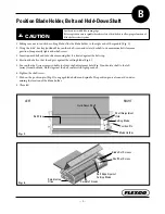
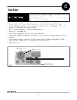
Position Blade Holder, Belt and Hold-Down Shaft
B
!
CAUTION
Avoid contact with blade cutting edge.
Before operation ensure spindle threads are free of dirt/debris to allow proper function of
blade holder release system.
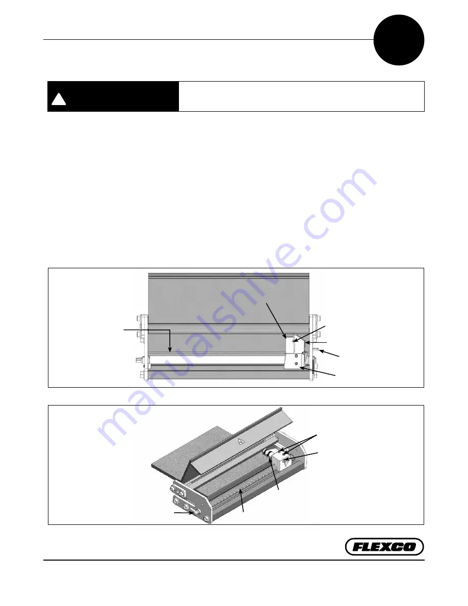
1. Taking care not to touch the cutting blade, slide the blade holder to the right end of the spindle. (Fig. 3).
2. Using the 9/64" hex key (included) loosen the shaft screw and rotate the shaft to its maximum belt clearance
position. Temporarily tighten the shaft screw.
3. Insert squared belt end into skiver ensuring that it is butted against the belt stop.
4. Position the belt so that the edge is against the cutting blade (Fig. 4).
5. Loosen the shaft screw, insert suitable tool into shaft adjustment hole (Fig. 3) and rotate shaft to the left
(away) from the blade. Hold it against the belt surface with light pressure.
6. Tighten the shaft screw.
7. Push on the position pin (Fig. 3) to engage blade holder and spindle. The position pin is also an aid in deter-
mining the location of the blade holder.
8. Close lid.
Fig. 4
Fig. 3
Shaft Adjustment
Hole
Cutting Blade
Position Pin
Blade Holder
Belt Stop
Spindle Hex
Drive
Blade Set Screws
Shaft Set Screw
Belt Edge Against
Cutting Blade
LEFT
RIGHT
Hold Down Shaft
Spindle Threads


