7
4.1 H-Type® Precleaner with HXF or HXF2 Tips (cont.)
Section 4 – Installation Instructions
Offset
Bracket
Mounting
Plate
Offset
Bracket
Chute wall
Offset
Bracket
Pulley
Pulley
Chute wall
Side View
Pivot Arm
Torque Arm
Mounting
Plate
Pivot Shaft
Bracket
Pole
Align the
four template
notches with
location marks
Intersecting
mark
Y
X
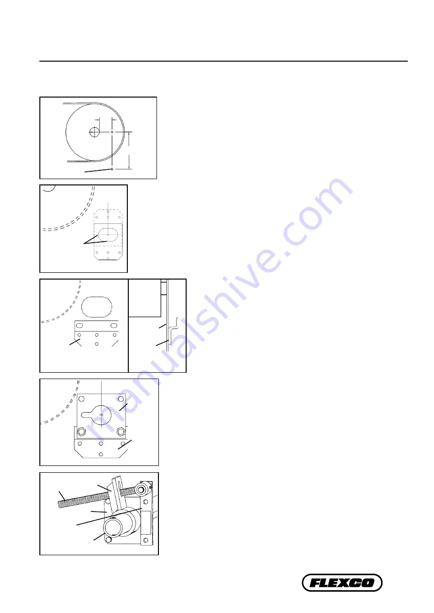
Fig. 7
Offset
Bracket
Mounting
Plate
Offset
Bracket
Chute wall
Offset
Bracket
Pulley
Pulley
Chute wall
Side View
Pivot Arm
Torque Arm
Mounting
Plate
Pivot Shaft
Bracket
Pole
Align the
four template
notches with
location marks
Intersecting
mark
Y
X
Fig. 4
8. Install offset brackets. Locate the offset brackets in the correct
position on the chute wall and bolt or weld in place (Fig. 5).
9. Install the pole. Slide the pole across the pulley and through the
chute openings. Allow the tips to hang down.
6. Locate offset bracket position. To locate the position of the offset bracket, position
offset bracket template with the large hole notches aligned with the layout lines on
the chute wall (Fig. 4). The template can be used with the bracket holes either below
or above the Y mark.
7. Cut pole opening. Using template provided, trace and cut the large opening and the
mounting holes.
5. Determine Y dimension.
From the X mark, draw a line vertically down to the
selected Y dimension and make a mark (Fig. 3). This is the correct position for the
center of the pole.
Offset
Bracket
Mounting
Plate
Offset
Bracket
Chute wall
Offset
Bracket
Pulley
Pulley
Chute wall
Side View
Pivot Arm
Torque Arm
Mounting
Plate
Pivot Shaft
Bracket
Pole
Align the
four template
notches with
location marks
Intersecting
mark
Y
X
Fig. 5
11. Position the pole. Rotate the pole upward until the tips touch the belt.
Center the tips across the belt. While applying light pressure on the center
tip, shift the loosened mounting plate until tips are contacting the belt
evenly across the full width. Lock cleaner into this position by tightening
mounting plate bolts.
12. Center the cleaner on the belt and lock in place. Center the tips on the
belt and install a pole lock collar on one end of the pole. Slide the collar
snugly up to the mounting plate and tighten.
Offset
Bracket
Mounting
Plate
Offset
Bracket
Chute wall
Offset
Bracket
Pulley
Pulley
Chute wall
Side View
Pivot Arm
Torque Arm
Mounting
Plate
Pivot Shaft
Bracket
Pole
Align the
four template
notches with
location marks
Intersecting
mark
Y
X
Fig. 6
Offset
Bracket
Mounting
Plate
Offset
Bracket
Chute wall
Offset
Bracket
Pulley
Pulley
Chute wall
Side View
Pivot Arm
Torque Arm
Mounting
Plate
Pivot Shaft
Bracket
Pole
Align the
four template
notches with
location marks
Intersecting
mark
Y
X
Fig. 3
10. Install mounting plates. On one side, slide mounting plate onto
pole and with the key slot positioned horizontally and toward
the pulley, bolt to the offset bracket, center in slots and tighten
(Fig. 6). On opposite side repeat the process, but do not tighten.
13. Install the QMT spring tensioner. Remove the adjusting nuts, bushings
and spring from the pivot rod. Insert the pivot arm through the slot in the
torque arm. Slide the torque arm onto the pole end (be sure the rotation
of the arm is correct to tension the blade) and rotate it until the pivot shaft
bracket lines up with the desired bolt holes (Fig. 7). Remove bolts, nuts and
washers from mounting plate and reinsert through the pivot shaft bracket
and mounting plate.


