background image

9

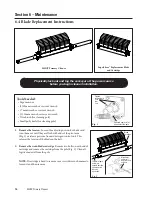
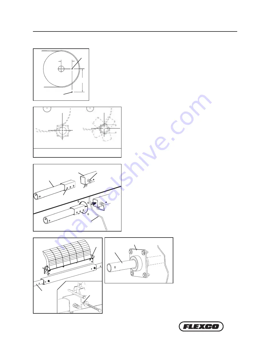
5.   Install the mounting bases. 

Bolt the mounting bases to the 

chute with the bolts provided 

(Fig. 5).

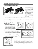
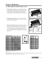
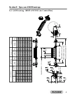
6.   Install the blade cartridge. 

Place the blade cartridge onto 

the centre pole. Adjust the 

extender poles until the holes 

align with the holes in 

the centre pole and lock the cartridge into place with the two bolts, 

washers and nuts (Fig. 6). NOTE: Be sure at least 150mm of the extender 

pole extends out of the mounting base on each side for tensioner 

installation. Adjust the extender poles in the centre pole if more or less 

length is needed.


Section 4 – Installation Instructions

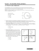
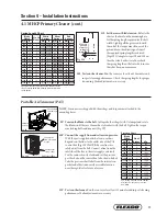
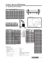
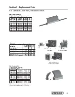
2.  Lay out the dimensions on the chute wall. Measure out the X dimension 

horizontally from the centre of the pulley shaft and mark. (NOTE: It may be 

easier to put a level on top of the pulley shaft, draw a horizontal line and then 

measure down half the diameter of the shaft and make a line from the front of 

the shaft. Now subtract half the pulley shaft diameter from the X coordinate 

and measure on the line and make a mark.) Then measure down vertically the 

Y dimension and mark. This is the correct position for the centre of the cleaner 

pole (Fig. 2). Lay out and mark the same dimensions on the other side.

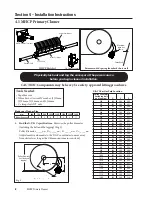
3.  Mark and cut the mounting base holes. Using the 

mounting base template provided in the instruction packet, 

position the large pole hole of the template on the chute with 

the hole notches aligned with the layout lines. Trace the pole 

hole and mounting holes (Fig. 3). Each base can be mounted 

in any position 360° around the pole as long as the pole’s 

centre point does not change. Cut the holes on both sides of 

the chute.

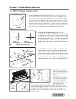
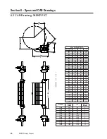
4.  Assemble the extender poles to the centre pole. Insert the 

extender poles through the chute holes and into the centre 

pole and make sure the locating bolt holes align with the 

centre pole holes (holes are offset to the lower half). Position 

the centre pole with the welded nuts and locking bolts on 

one side facing down and on the adjoining side facing away 

from the head pulley (Fig. 4). Leave the locking bolts loose.

4. 1  MHCP Primary Cleaner (cont.)

mark

Y

X

mark

Center large template hole notches on pole center mark, 

rotate to desired angle and trace holes

Template for

PST mounting base

Template for

AWT/NT mounting base

Blade 

Cartridge

6" of pole end 

must extend 

outside the 

mounting base 

on each side

Align holes 

and install 

bolts, washers 

and nuts

Extender 

Pole

Mounting Plate 

(Pst Shown)

Chute wall 

(cut away)

Chute wall 

(cut away)

Center Pole

Extender Pole

Must be facing 

away from 

head pulley

Locating bolt 

holes

Locking 

Bolts

Must align with 

extender pole 

holes

Must be 

facing down

Fig. 2

mark

Y

X

mark

Center large template hole notches on pole center mark, 

rotate to desired angle and trace holes

Template for

PST mounting base

Template for

AWT/NT mounting base

Blade 

Cartridge

6" of pole end 

must extend 

outside the 

mounting base 

on each side

Align holes 

and install 

bolts, washers 

and nuts

Extender 

Pole

Mounting Plate 

(Pst Shown)

Chute wall 

(cut away)

Chute wall 

(cut away)

Center Pole

Extender Pole

Must be facing 

away from 

head pulley

Locating bolt 

holes

Locking 

Bolts

Must align with 

extender pole 

holes

Must be 

facing down

Fig. 3

mark

Y

X

mark

Center large template hole notches on pole center mark, 

rotate to desired angle and trace holes

Template for

PST mounting base

Template for

AWT/NT mounting base

Blade 

Cartridge

6" of pole end 

must extend 

outside the 

mounting base 

on each side

Align holes 

and install 

bolts, washers 

and nuts

Extender 

Pole

Mounting Plate 

(Pst Shown)

Chute wall 

(cut away)

Chute wall 

(cut away)

Center Pole

Extender Pole

Must be facing 

away from 

head pulley

Locating bolt 

holes

Locking 

Bolts

Must align with 

extender pole 

holes

Must be 

facing down

Fig. 4

mark

Y

X

mark

Center large template hole notches on pole center mark, 

rotate to desired angle and trace holes

Template for

PST mounting base

Template for

AWT/NT mounting base

Blade 

Cartridge

6" of pole end 

must extend 

outside the 

mounting base 

on each side

Align holes 

and install 

bolts, washers 

and nuts

Extender 

Pole

Mounting Plate 

(Pst Shown)

Chute wall 

(cut away)

Chute wall 

(cut away)

Center Pole

Extender Pole

Must be facing 

away from 

head pulley

Locating bolt 

holes

Locking 

Bolts

Must align with 

extender pole 

holes

Must be 

facing down

Fig. 5

Fig. 6

Blade 

Cartridge

150 mm of pole 

end must extend 

outside the 

mounting base 

on each side

Align holes 

and install 

bolts, washers 

and nuts

Summary of Contents for MHCP

Page 1: ...MHCP Primary Cleaner Installation Operation and Maintenance Manual www flexco com www flexco com...

Page 2: ...Purchased From _____________________________________________________________ Installation Date _____________________________________________________________ This information will be helpful for any fu...

Page 3: ...ation Checklist and Testing 12 5 1 Pre Op Checklist 12 5 2 Test Run the Conveyor 12 Section 6 Maintenance 13 6 1 New Installation Inspection 13 6 2 Routine Visual Inspection 13 6 3 Routine Physical In...

Page 4: ...11 608 4180 Visit www flexco com for other Flexco locations and products Please read this manual thoroughly and pass it on to any others who will be directly responsible for installation operation an...

Page 5: ...ps Clear the conveyor belt or clamp securely in place Use Personal Protective Equipment PPE Safety eyewear Hardhats Safety footwear Close quarters springs and heavy components create a worksite that c...

Page 6: ...sure all the parts are included Review the Tools Needed list on the top of the installation instructions Check the conveyor site Will the cleaner be installed on a chute Are there obstructions that ma...

Page 7: ...em In the example we decide to lower the pole 50mm to clear the support structure 2 Write down known dimensions We can now determine two of the three required dimension which will allow us to find the...

Page 8: ...650 330 365 492 675 343 365 502 700 356 365 511 725 368 365 518 750 381 365 527 775 394 365 537 800 406 365 546 825 419 365 556 850 432 365 565 875 445 365 575 900 457 365 584 925 470 365 594 950 483...

Page 9: ...and locking bolts on one side facing down and on the adjoining side facing away from the head pulley Fig 4 Leave the locking bolts loose 4 1 MHCP Primary Cleaner cont mark Y X mark Center large templa...

Page 10: ...orque arm until the pivot rod is against the end of the slot nearest the pole Tighten the locking bolts and jam nuts on the torque arm Fig 12S NOTE The torque arm should be up against the mounting bas...

Page 11: ...ulator of Washer orque Arm Measure from top of washer to top of torque arm 13S Setthecorrectbladetension Refertothe chartorthedecalonthemountingbase forthespringlengthrequiredforthebelt width Lightlyp...

Page 12: ...ure that all installation materials and tools have been removed from the belt and the conveyor area 5 2 Test Run the Conveyor Run the conveyor for at least 15 minutes and inspect the cleaning performa...

Page 13: ...n or if there are areas that are dirty If the blade is worn out and needs to be replaced If there is damage to the blade or other cleaner components If fugitive material is built up on the cleaner or...

Page 14: ...2 Remove the worn blade cartridge Remove two bolts on each end of cartridge and remove the cartridge from the pole Fig 2 Clean all fugitive material from the pole NOTE If cartridge is hard to remove u...

Page 15: ...e Align holes and install bolts washers and nuts Fig 4 Locking Bolts And Jam Nuts Collapse Air Bags of Washer orque Arm Measure from top of washer to top of torque arm Fig 5 6 del eje y se debe extend...

Page 16: ...__ Service Quote ___________________ Activity ______________________________________________________________________________________ _____________________ Date ___________________ Work done by _______...

Page 17: ...s No Pole Condition Good Bent Worn Lagging Side Lag Ceramic Rubber Other None Condition of lagging Good Bad Other_ _______________________________________________________ Cleaner s Overall Performance...

Page 18: ...spring length kPa chart Unusual wear or damage to blade Mechanical splice damaging blade Repair skive or replace splice Belt damaged or ripped Repair or replace belt Cleaner not correctly located Ver...

Page 19: ...ng wear Available for Belt Widths 600 to 2100 mm Other sizes available upon request CEMA Cleaner Rating Class 5 Maximum Overall Pole Length Maximum Conveyor Span Centre Pole Length Top of washer to to...

Page 20: ...HART Diameter X Y C 500 254 365 445 525 267 365 451 550 279 365 460 575 292 365 467 600 305 365 476 625 318 365 483 650 330 365 492 675 343 365 502 700 356 365 511 725 368 365 518 750 381 365 527 775...

Page 21: ...30P 78724 MHP CP30 75962 MHCP 2BC30 76639 36 900 94 2380 5 MHCP 36P 78725 MHP CP36 75963 MHCP 2BC36 76640 42 1050 100 2530 6 MHCP 42P 78726 MHP CP42 75964 MHCP 2BC42 76488 48 1200 106 2680 7 MHCP 48P...

Page 22: ...1200mm PSTS W 75898 0 8 10a Tension Spring Silver 1 ea for belts 1350 2100mm PSTS S 75899 1 4 11 Bushing Kit 2 ea for White Silver Tensioners QMTBK W 76098 0 1 12 Pole Bearing Assy for cleaners shipp...

Page 23: ...PA30 75946 54 9 900 36 MHCP BPA36 75947 61 8 1050 42 MHCP BPA42 75948 68 6 1200 48 MHCP BPA48 75949 75 4 1350 54 MHCP BPA54 75950 82 3 1500 60 MHCP BPA60 75951 89 1 1800 72 MHCP BPA72 75952 102 8 2100...

Page 24: ......

Page 25: ......

Page 26: ......

Page 27: ...the tail pulley Exclusive blade design quickly spirals debris off the belt Economical and easy to service Available in vee or diagonal models PT Max Belt Trainer Belt Ploughs Limited space cleaners f...

Page 28: ...rldwide through superior service and innovation 236 Albert Amon Rd Meadowdale Ext 7 Germiston 1614 South Africa Tel 27 11 608 4180 Fax 27 11 454 5821 E mail flexco flexco co za Visit www flexco com fo...

Reviews: