8
U-Type
®
Secondary Cleaner
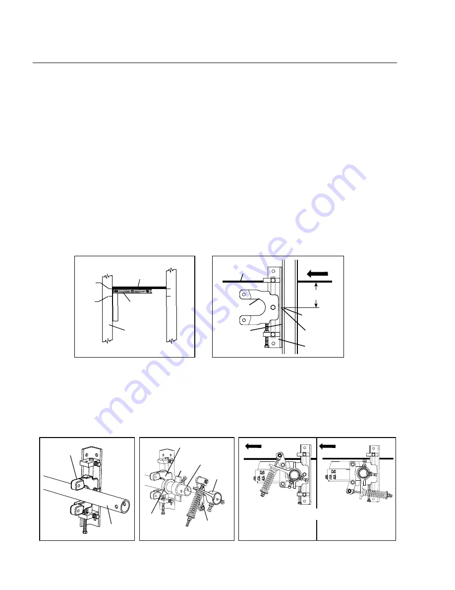
3U. Install the cleaner pole into the slider plates.
a. Set pole ends into slider plate on both sides (Fig. 3Ua).
b. Slide pole bearings onto both ends of the pole with flange facing away from the belt (Fig. 3Ub).
c. Slide stop collar onto both ends of the pole (Fig. 3Ub). Do not tighten at this time.
d. Slide torque arms onto both ends of pole and attach both pivot shaft brackets to slider plates (Fig. 3Ub).
Blade and torque arm must face either in the direction of belt travel (Fig. 3Uc), or if clearance is an issue,
switch to rotated tensioner configuration and assemble as shown (Fig. 3Ud).
e. Move slider plate to bottom of bracket to allow blade to rotate up into position in the next steps.
Fig. 3Ua
Repeat at
other end
Repeat at
other end
Slider Plate
Pole
Pole Bearing
(flange facing out)
Pole
- OR -
Fig. 3Ub
Slider Plate
Torque
Arm
Stop
Collar
Pivot Shaft
Bracket
Belt Direction
Belt Direction
Blade and torque arm
must face in the direction
of belt travel
If clearance is an issue
switch to rotated tensioner
configuration and assemble
as shown.
Section 4 - Installation Instructions
4.1 U-Type® Secondary Cleaner
Fig. 3Ud
Fig. 3Uc
Fig. 2Ua
2U. Install mounting brackets.
a. Using a level, lightly raise return side belt (take out cupping or sagging on edges) to find belt's true parallel path to
the structure; and mark reference point #1 on structure. Measure down 75mm (3”) from reference point #1 and
mark reference point #2 (Fig. 2Ua). Make sure brackets are the same distance away from head pulley or a reference
point on both sides of the structure. If there is no structure to mount to, install mounting bracket kit first.
b. Position mounting brackets so centerline marks on brackets are in line with reference points #2 on the structure
(Fig. 2Ub).
c. Clamp or weld into position.
Return
Side Belt
Belt Direction
Mounting
Bracket
Ref.
Point #1
Level
Return
Side Belt
Structure
Right
Side
Left
Side
#1
#2
Ref.
Point #2
Ref.
Point #2
Fig. 2Ub
Centerline on
Bracket
Bracket flush
to structure or
mounting kit
Slider Plate
3"
(75mm)
UST Tensioner Instructions
1. Choose conveyor location where cleaner will be installed.
The U-Type may be positioned at any spot from where belt leaves head pulley on down the conveyor line (see
positions A to B). If a chute area is too small due to a snub pulley, it may be necessary to mount cleaner behind
chute (see position C). In chute applications a minimum of 150-200mm (6”-8”) is required between cleaner and
chute wall to prevent clogging of material.
NOTE: For U-Type cleaners using UST Tensioners, proceed to Steps 2U - 7U.
For U-Types using J-Bolt Tensioners, skip ahead to Steps 2J - 8J on Page 10.


