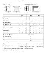
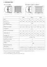
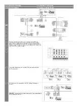

S1
S2
S3
L1
L2
L3
XL2
XL3
A
<3,0
<3,0
<3,0
2,5-8,0
2,5-8,0
2,5-8,0
2,5-8,0
2,5-8,0
B 2,5-7,0
2,5-6,0
2,5-6,0
2,5-9,5
2,5-8,5
2,5-8,0
2,5-9,5
2,5-9,0
C
>0,3
>0,3
>0,3
>0,3
>0,3
>0,3
>0,3
>0,3
D
>0,5
>0,5
>0,5
>0,5
>0,5
>0,5
>0,5
>0,5
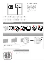
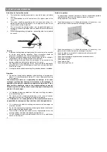
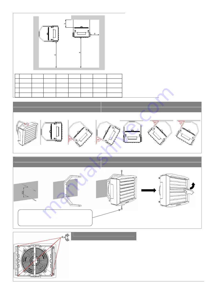
Fan
heaters
can
be
mounted to vertical or
horizontal partitions in any
position.
During
the
montage,
the
minimal
distances from the walls
and ceiling have to be
kept.
U-profiles should be mounted in corners as drawing
shows. Is not allowed to screw profiles in other
places.
!!!
3. INSTALLATION
3.1. INSTALLATION –BRACKET
3.2. ASSEMBLY INSTRUCTIONS
M8 screws are in set with bracket
3.3 U-PROFILES (optional)