background image

60

2.    MAINTENANCE

SUPPOR

T

 C

ENTRE

CODE

FAULT

POSSIBLE CAUSE

SOLUTION

RESET

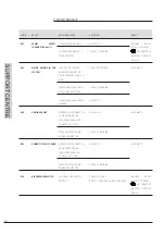
E03

FUMES SAFETY 
THERMOFUSE (102°C)

THERMOFUSE BROKEN;

REPLACE IT;

MANUAL 

RESET 

(HOLD THE RESET ‘

’ KEY FROM THE 

MASTER CONTROL 

PANEL).

THERMOFUSE CABLE 

DISCONNECTED.

CHECK THE WIRING.

E04

WATER MISSING IN THE 
SYSTEM

INSUFFICIENT WATER 

PRESSURE INSIDE THE 

SYSTEM (LOWER THAN 0.3 

BAR);

LOAD THE SYSTEM;

AUTOMATIC.

WATER PRESSURE SWITCH 

CABLE DISCONNECTED;

CHECK THE WIRING;

WATER PRESSURE SWITCH 

BROKEN.

REPLACE IT.

E05

HEATING PROBE

BROKEN OR INCORRECTLY 

CALIBRATED PROBE 

(RESISTANCE VALUE 10 

KOHM AT 25 °C NTC);

REPLACE IT;

AUTOMATIC.

DISCONNECTED OR WET 

PROBE CONNECTOR.

CHECK THE WIRING.

E06

DOMESTIC CIRCUIT PROBE

BROKEN OR INCORRECTLY 

CALIBRATED PROBE 

(RESISTANCE VALUE 10 

KOHM AT 25 °C NTC);

REPLACE IT;

AUTOMATIC.

DISCONNECTED OR WET 

PROBE CONNECTOR.

CHECK THE WIRING.

E14

AIR PRESSURE SWITCH

AIR PRESSURE SWITCH 

TRIPPED

CHECK FLUE GAS

DUCTS, CHECK CABLE, REPLACE PART

MANUAL RESET 

(HOLD THE RESET ‘

’ KEY FROM THE 

MASTER CONTROL 

PANEL).

Summary of Contents for R1K 75 RAIN

Page 1: ...Installation and Maintenance Manual for model Premix condensing system boiler only heating suitable for outdoor installation R1K 75 RAIN ...

Page 2: ... 1 15 ELECTRICAL CONNECTION 22 1 1 16 POWER SUPPLY 23 1 1 17 OPTIONAL ELECTRICAL CONNECTIONS 24 1 1 18 FUME EXHAUST FITTINGS 26 2 SUPPORT CENTRE SECTION 29 2 1 FIRST START UP 30 2 1 1 PRELIMINARY OPERATIONS FOR FIRST START UP 30 2 1 2 BOILER COMMISSIONING 31 2 1 3 CO2 VALUE CHECK AND CALIBRATION 32 2 1 4 ACCESSING AND PROGRAMMING THE PARAMETERS 33 2 1 5 DIGITECH CS PARAMETERS TABLE MIAH406 36 2 1 ...

Page 3: ...G THE BOILER 54 2 2 14 ACCESSING THE MASTER ELECTRONIC BOARD 55 2 2 15 ACCESSING THE SLAVE ELECTRONIC BOARD 56 2 2 16 SYSTEM EMPTYING 57 2 2 17 FAULT SIGNALLING CODES 58 2 2 18 ACTIVE FUNCTIONS SIGNALLING CODES 63 2 2 4 GAS CONVERSION 64 ...

Page 4: ...ed in the text marked with numbers or letters See chap chapter name this entry indicates another section in the Manual that you should refer to Device this term is used referring to the boiler DANGER It identifies an information related to a general danger that if not complied with may cause serious personal damage or even death ATTENTION It identifies an information that if not complied with may ...

Page 5: ...e information on the warranty validity its duration the obligations and the exemptions please consult the First start up certificate attached to this manual The manufacturer reserves the right to modify the tools and relative technical documentation without any obligation to third parties neither will the company be held responsible for any inaccuracies in this handbook deriving from printing or t...

Page 6: ...d be performed only by qualified personnel having the appropriate technical training in the field for the installation and maintenance of components of civil and industrial domestic hot water production and heating plants 1 INSTALLER SECTION 1 INSTALLER SECTION ...

Page 7: ...ormance The location must be properly vented through an air vent The air vent must be placed at floor level to prevent it from being obstructed protected by a grid that does not hamper the useful section of passage The device is suitable for use with the type of gas available by checking the boiler data plate placed on the inner side of the front casing Make sure that the tubes and couplings are p...

Page 8: ...stances kit see chapter ANTI FREEZE PROTECTION WARNING The manufacturer will not be held responsible for damages caused by incorrect installation not in conformity with the over mentioned instructions and not protected adequately from the freeze 1 1 3 REFERENCE LEGISLATION The installation must be realized according to the requirements of current legislation and in compliance with local technical ...

Page 9: ...ATION INSTALLER 1 1 4 BOILER OVERALL DIMENSIONS 1 1 5 JIG 350 160 600 977 730 R SC G A 93 162 67 155 180 85 310 215 195 320 SC R HEATING RETURN Ø 1 1 2 G GAS Ø 3 4 A HEATING FLOW Ø 1 1 2 SC CONDENSATE DRAIN Ø 25 mm ...

Page 10: ...ilo Yonos PARA RS 15 7 5 0 0 5 1 0 1 5 2 0 2 5 3 0 3 5 0 0 2 0 4 0 6 0 8 1 0 2 0 4 6 8 10 12 14 0 1 2 3 4 5 6 7 8 0 10 20 30 40 50 60 70 80 0 0 5 1 0 1 5 2 0 2 5 3 0 3 5 4 0 4 0 0 20 40 60 3780 25PWM1 4270 15PWM1 4770 5PWM1 3280 35PWM1 2780 45PWM1 2280 55PWM1 1780 65PWM1 1290 75 m ax p kPa H m P1 W Q m h Q l s Q Igpm Q m h max PWM1 790 85PWM1 ...

Page 11: ...se position 1 to adjust maximum Co2 Natural Gas 9 3 9 1 LPG 10 3 10 1 Note Turn screw anti clock wise to increase Refer to Pg 32 for more details Use position 2 to adjust minimum Co2 Natural Gas 9 8 8 LPG 9 9 9 7 Note Turn screw clockwise 2 1 Gas Valve to increase Refer to Pg 32 for more details Use position 1 to adjust maximum Co2 Natural Gas 9 3 9 1 LPG 10 4 10 2 Note Turn screw anti clock wise ...

Page 12: ...de the condensate module WARNING The boiler must be installed only on a vertical solid wall able to sustain its weight WARNING The boilers have the electrical protection degree IPX5D The outdoor installation in partially protected environments platform roof balcony see fig 2 is allowed in compliance with the related standards The Company is not held liable for installations in environments with a ...

Page 13: ...nly when masonry works are completed For assembly follow the instructions below 1 With the help of a spirit level fix the mounting template to the wall where you intend to install the boiler mark the points to insert the ø10 dowel screws and points for the heating flow and heating return system s connections 2 Make the holes and fix the frame to wall Figure 1 3 Hook the boiler using the slots on t...

Page 14: ...ESTIC CIRCUIT In order to prevent limestone build up and damages to the domestic water heat exchanger the hardness of the domestic supply water should not exceed 15 f However please check the characteristics of the water used and install suitable treating devices The heat exchanger coil cleaning frequency depends on the hardness of the supply water and on the presence of solid residues or impuriti...

Page 15: ... suspected that the system might be dirty or particularly clogged and at the next loading with new treated water Water treatment In order to preserve the integrity of the water fume exchanger and to guarantee optimal thermal exchanges it is necessary that the water of the primary circuit circulating inside the exchanger of thecondensateboiler hasthecharacteristicsdefined and constant in time To ob...

Page 16: ...not fall under the values indicated below should be softened Moreover additives can be added in order to maintain the limestone into the solution The hardness must be periodically checked and registered Acidity 7 pH 8 5 Conductivity 400 μs cm at 25 C Chlorides 125 mg l Iron 0 5 mg l Copper 0 1 mg l If the above indicated limits are exceeded a water must be chemically treated The type of treatment ...

Page 17: ...tem are not blocked 4 open the general domestic water input tap and load the system by exhaling all the air 5 use pressure gauge present in the system to make sure that the system pressure reaches the design value 6 after performing this operation make sure that the loading tap is properly closed 7 Open the air relief valves of the radiators and check the air removal process When the water starts ...

Page 18: ...duces a significant quantity of condensate during operation This condensate has an acid pH of 3 5 Observe the national standard in force and the local regulations for the disposal of the condensate produced by the boiler The designer according to the power of the system and the intended use of the building is bound to evaluate the acceptance of systems in order to neutralise the acid condensate Th...

Page 19: ... to determine the pH Then the neutralised condensate can be transported into the sewage system MAINTENANCE The pH parameters must be comprised between 7 and 8 5 Every six months it is necessary to establish the PH of the treated condensate inside the neutraliser Immerse a litmus paper or a suitable digital tool in the condensate near the tapped draining connection for about 2 seconds and thus lay ...

Page 20: ...hes the 30 C and in presence of a return sensor until the heating return water temperature reaches the 20 C The system starts even if on the display appears OFF as long as the boiler is connected to the power 230 V and gas supply For long periods of standby please empty the boiler and the plant If the temperature goes below 10 centigrades please fill the plant with anti freeze liquid CLEANPASS FLU...

Page 21: ...R The equipment is electrically safe only if it is properly connected to an efficient grounding system performed in compliance with the safety standards in force You should check this essential safety requirement If in doubt request an accurate check of the electrical system performed by qualified staff as the manufacturer is not responsible for any damages caused by lack of grounding system Make ...

Page 22: ...below instructions DANGER Cut off the voltage from the main switch remove the casing bottom cover see Chapter ACCESSING THE BOILER disconnect the SPM male Plug and make the connections see fig 1 When finished reconnect the male plug to the female socket and then remount the casing bottom cover N L 1 2 3 4 SPM L N B3 S3 T2 T1 N T L 230 V 50 Hz fig 1 blue yellow green brown ...

Page 23: ...on polarized conductors to the B3 S3 contacts For the room thermostat or Remote control first remove the bridge on the T2 T1 contacts and then connect the two non polarized conductors to the T2 T1 contacts When finished reconnect the male plug to the female socket and then remount the fitting cover NOTA BENE In case of simultaneous presence of external probe and remote control the modulation board...

Page 24: ...se of the control panel see chapter ACCESSING THE MASTER ELECTRONIC BOARD after removing the crankcase connect the items below to the electronic board see fig 1 After performing these operations remount the crankcase and the front casing TP CT BUS 0 10V GND BUS 11 10 9 8 7 12 13 14 15 16 17 M12 M9 M7 M5 M2 M4 M8 M10 M15 M16 1 2 3 4 57 61 60 59 58 44 43 42 41 40 39 38 37 36 35 34 33 32 31 30 29 28 ...

Page 25: ...ct carefully follow the technical standards in force Suction and discharge systems tailored to individual installations must be protected with accessories that prevent the ingress of foreign objects and atmospheric agents INSTALLATION REQUIREMENTS For United Kingdom comply with the latest building regulation 2010 Part J2 Discharge of products of combustion and local authority for minimum clearance...

Page 26: ...27 1 INSTALLATION SUPPORT CENTRE ...

Page 27: ...a vertical flue exhaust and air intake from the boiler installation site It allows to exhaust the combustion gases by means of a pipe and to intake the air directly from the hole located onto the room sealed chamber top PLEASE SEE THE MAXIMUM DISCHARGE IN THE TABLE IN CHAPTER TECHNICAL DATA 446 250 ...

Page 28: ...fied with the operation please instruct the consumer on the correct method of operation 1 SUPPORT CENTRE SECTION 2 SUPPORT CENTRE SECTION All operations described below relative to first start up maintenance and replacement should be performed only by qualified personnel and authorized by FLEXIHEAT UK ...

Page 29: ...properly make sure that the combustion air adduction and fumes and condensate discharge take place properly in compliance with the Local and National Laws and Standards in force make sure that the fumes discharge tube and its connection to the fume exhaust duct comply with the requirements of the Local and National Laws and Standards make sure that the heating system gate valves are open make sure...

Page 30: ...inutes by shutting off the power supply and then restoring it After completing the above mentioned operations open the gas tap Use the button to select the desired operation mode If the symbol is displayed fixed it means that the function was activated the burner will start as soon as the thermostat contact is closed if the flame is missing the board will repeat the start up operations after post ...

Page 31: ...rn the screw clockwise and vice versa if you want to decrease it Once completed the adjustment tighten the protection screw A fig 2 on the Off Set adjuster FOR MAXIMUM HEATING POWER Press the key of the heating in order to calibrate the maximum heating power Make sure that the CO2 value complies with the requirements indicated in chapter Technical data otherwise adjust using screw 1 fig 2 of the g...

Page 32: ...ol panel 1 see figure except for the parameters with which it is possible to set the power of a single unit P00 P10 P11 P12 P13 and P14 in this case act also from the slave control panel 2 see figure To access the parameters menu and adjust their values follow the procedure below 1 Press the button to select the OFF mode displayed using the symbol 1 2 ...

Page 33: ... time the keys and until on the display appears the symbol with the message P00 and release the keys and 3 Use the keys and of the heating circuit to select the parameter to be edited 4 Use the keys and of the S symbol to change the value of the parameter ...

Page 34: ...nted 6 To exit the parameters menu hold at the same time the keys and and wait for the symbol to appear on the display 7 In order for the modifications performed by the master control panel be set even on the slave board switch off and on the power to the boiler Wait the necessary time for the operation about 30 seconds until the symbol no longer appears on the display ...

Page 35: ...TRUCTION IN CHAPTER GAS TRANSFORMATION BEFORE CHANGING THIS PARAMETER 0 1 0 METHANE 1 GPL P03 SETTING THE HEATING TEMPERATURE IN CASE OF DIRECT SUPPLY BY A BOILER OF A LOW TEMPERATURE SYSTEM INSTALL A SECURITY THERMOSTAT ON THE DELIVERY WHICH INTERRUPTS THE OPERATION OF THE BOILER IN CASE OF HIGH DELIVERY TEMPERATURE THE COMPANY IS NOT HELD LIABLE FOR RESULTING DAMAGES TO PERSONS OR THINGS DUE TO ...

Page 36: ... START ONLY MASTER 2 START ONLY SLAVE 3 BOTH TURNED ON P07 HEATING TIMING THROUGH THIS PARAMETER YOU CAN SET THE MINIMUM TIME FOR WHICH THE BURNER WILL BE TURNED OFF ONCE THE HEATING TEMPERATURE REACHED THE USER SET TEMPERATURE 0 90 VALUE EXPRESSED IN MULTIPLES OF 5 SECONDS PRE SET AT 36 X 5 180 SECONDS P08 POST CIRCULATION HEATING TIMING THROUGH THIS PARAMETER YOU CAN SET THE PUMP DURATION OF OPE...

Page 37: ... 1HZ 30 RPM P12 HEATING FAN MINIMUM SPEED ADJUSTMENT THROUGH THIS PARAMETER YOU CAN SET THE FAN MINIMUM SPEED IN HEATING PHASE THAT CORRESPONDS TO THE MINIMUM BURNER POWER DURING A REQUEST TO OPERATE IN HEATING MODE SEE CHAPTER HEAT CAPACITY DIAGRAM KW ELECTRIC FAN FREQUENCY HZ THE VALUE IS PRE SET BASED ON THE SET POWER SEE PARAMETER P00 AND ON THE GAS TYPE SEE PARAMETER P02 CHANGE THE PARAMETER ...

Page 38: ... VALUE IS EXPRESSED IN HERTZ 1HZ 30 RPM P15 ANTI LEGIONELLA FUNCTION ONLY FOR THE VERSION WITH REMOTE BOILER SUPPLY SYSTEM THROUGH THIS PARAMETER YOU CAN ACTIVATE DEACTIVATE ANTI LEGIONELLA HEAT TREATMENT OF THE ACCUMULATION BOILER EVERY 7 DAYS THE WATER TEMPERATURE INSIDE THE ACCUMULATION BOILER IS HEATED BEYOND 60 C THUS GENERATING A BURNING HAZARD KEEP UNDER CONTROL SUCH DOMESTIC HOT WATER TREA...

Page 39: ...NG INTO ACCOUNT THE HOUSE INSULATION DEGREE THE VALUES OF THE DELIVERY TEMPERATURES TM REFER TO STANDARD SYSTEMS 30 80 C OR FLOOR SYSTEMS 25 45 C THE SYSTEM TYPE CAN BE SET FROM PARAMETER P03 0 30 SET BY DEFAULT AT 15 THE NUMBERING OF THE VALUE CORRESPONDS TO KD CURVES ON THE CHART SEE CHART BELOW P17 BOILER LOADING SETPOINT DIFFERENTIAL ONLY FOR THE VERSION WITH REMOTE BOILER SUPPLY SYSTEM BY MEA...

Page 40: ...LE MAXIMUM DOMESTIC TEMPERATURE 45 75 THE VALUE IS EXPRESSED IN C P22 SET POINT T DELIVERY RETURN THROUGH THIS PARAMETER YOU CAN SET THE TEMPERATURE DIFFERENCE BETWEEN DELIVERY AND RETURN 0 0 DISABLED 10 40 THE VALUE IS EXPRESSED IN C P23 MODULATING PUMP MINIMUM SPEED THROUGH THIS PARAMETER YOU CAN SET THE MINIMUM SPEED VALUE OF THE MODULATING PUMP DURING A REQUEST TO OPERATE IN HEATING MODE 50 70...

Page 41: ...CTED REMOTE P30 SETTING THE TEMPERATURE MEASUREMENT UNIT THROUGHTHISPARAMETER YOUCANSELECTTHEMEASUREMENT UNIT OF THE DISPLAYED TEMPERATURE CELSIUS C OR FAHRENHEIT F DEGREES 0 1 0 C 1 F P31 SELECTION OF THE COUNTRY OF DESTINATION BY CHANGING THIS PARAMETER THE CONTROL PARAMETERS OF THE COMBUSTION ARE AUTOMATICALLY CONFIGURED ACCORDING TO THE VALUES PRE SET IN THE COUNTRY OF DESTINATION OF THE PRODU...

Page 42: ...ARY BOARD BY MEANS OF THIS PARAMETER IT IS POSSIBLE TO ENABLE THE AUXILIARY BOARD FOR THE EXPANSION OF THE RESOURCES WHEN THE SOLAR AUXILIARY BOARD IS CONNECTED TO THE BOILER BOARD AUTOMATICALLY THE VALUE OF THIS PARAMETER BECOMES 1 BUT IF THE SOLAR AUXILIARY BOARD IS SUCCESSIVELY DISCOUNNECTED THE DISPLAY OF THE CONTROL PANEL OF THE BOILER WILL DISPLAY THE ERROR E31 IN THIS CASE IN ORDER TO DEACT...

Page 43: ...NIT 50 kW GAS TYPE MINIMUM FREQUENCY DURING HEATING MAXIMUM FREQUENCY DURING HEATING Natural Gas Black Hz 53 247 Universal LPG Orange Hz 53 240 Universal LPG Orange Natural Gas Black 0 5 10 15 20 25 30 35 40 45 50 55 35 50 65 80 95 110 125 140 155 170 185 200 215 230 245 HEAT CAPACITY kW FREQUENCY Hz ...

Page 44: ... THE MASTER UNIT 25 kW GAS TYPE MINIMUM HEATING FREQUENCY MAXIMUM HEATING FREQUENCY Natural Gas Black Hz 50 192 Universal LPG Orange Hz 50 190 Universal LPG Orange Natural Gas Black 2 4 6 8 10 12 14 16 18 20 22 24 26 35 50 65 80 95 110 125 140 155 170 185 200 HEAT CAPACITY kW FREQUENCY Hz ...

Page 45: ...ion and light up electrodes from incrustations paying attention to respect the distances with respect to the burner check the heating circuit safety systems limit temperature safety thermostat limit pressure safety check the pre load pressure of the expansion vessel make sure that the permanent ventilation outlets are present correctly sized and functioning based on the installed devices Respect t...

Page 46: ... LPG CO2 at minimum heat capacity Universal LPG CO at nominal heat capacity ppm Fumes mass at nominal heat capacity g s Fumes mass at minimum heat capacity g s NOx class class Weighted Nox 0 O2 mg kWh mg kWh 10 3 10 1 50kW 10 4 10 2 25kW 9 9 9 7 50kW 9 95 9 85 25kW 68 33 14 1 32 6 51 Heating circuit Adjustable heating temperature C Maximum operating temperature for heating circuit C Maximum operat...

Page 47: ...ure Natural Gas kPa 1 13 Heating Max fan speed Natural Gas Hz 247 50kW 192 25kW Heating Min fan speed Natural Gas Hz 53 50kW 50 25kW Fuel consumption Natural Gas MJ h 297 Nominal Supply pressure Universal LPG kPa 2 75 Heating Max fan speed Universal LPG Hz 240 50kW 190 25kW Heating Min fan speed Universal LPG Hz 53 50kW 50 25kW Fuel consumption Universal LPG MJ h 297 ...

Page 48: ...AS VALVE 9 AUTOMATIC AIR RELIEF VALVE 10 MANUAL AIR RELIEF VALVE 11 HEATING PROBE 12 SAFETY THERMOSTAT 13 LIGHT UP ELECTRODE 14 AIR SUCTION TUBE 15 START UP TRANSFORMER 16 PROPORTIONAL VENTURI 17 SAFETY VALVE 3 bar 18 WATER PRESSURE GAUGE 19 COLLECTOR PROBE 20 MASTER UNIT HEAT EXCHANGER 21 AIR PRESSURE SWITCH 1 2 3 4 5 16 7 8 9 11 12 13 15 6 17 18 19 10 14 4 3 1 16 8 14 15 6 7 11 20 12 13 9 10 21 ...

Page 49: ...LECTRIC FAN 5 RETURN PROBE 6 CIRCULATOR 7 GAS VALVE 8 SYSTEM DRAINING TAP 9 AUTOMATIC AIR RELIEF VALVE 10 HEATING PROBE 11 SAFETY THERMOSTAT 12 AIR SUCTION TUBE 13 PROPORTIONAL VENTURI 14 CONDENSATE COLLECTION SIPHON 15 SAFETY VALVE 3 bar 16 COLLECTOR PROBE 17 WATER PRESSURE SWITCH 18 MASTER HEAT EXCHANGER 19 MANUAL AIR RELIEF VALVE R A G 1 2 3 4 6 10 11 3 13 14 15 5 1 10 18 11 9 5 14 7 12 6 4 13 ...

Page 50: ...51 2 MAINTENANCE SUPPORT CENTRE ...

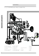
Page 51: ... 26 62 63 64 65 66 67 68 51 52 53 54 55 56 5 6 M13 M14 24V HS PWM GND PM SRi ma ce M6 1 2 6 5 eBus GND TXOUT RXIN GND 24V SC L N SM SPM SE TA 220 V 50 Hz L N B3 S3 T2 T1 N T L B3 S3 T2 T1 N T L PA 2 1 1 3 3 ma ce ER DETECTION ELECTRODE TS SAFETY THERMOSTAT CE BLUE EA START UP ELECTRODE SM MODBUS BOARD MA BROWN PM MODULATING CIRCULATOR SR HEATING PROBE PA AIR PRESSURE SWITCH AR ORANGE VG GAS VALVE ...

Page 52: ...CTRIC FAN L LINE TB LOCK OUT THERMOSTAT TRA START UP TRANSFORMER TF FUMES THERMOFUSE 102 C N NEUTRAL SPM MALE PLUG SM MODBUS BOARD SRI SYSTEM RETURN PROBE SPF FEMALE SOCKET ma ce ma ce ma ce ma gi bi gr EV ce ma ce ma EA VG Tra ce ma ER TS TF SR ar ar ce ma ma ce ne ne MP Pacq 11 10 9 8 7 12 13 14 15 16 17 M12 M9 M7 M5 M2 M4 M8 M10 M15 M16 1 2 3 4 57 61 60 59 58 44 43 42 41 40 39 38 37 36 35 34 33...

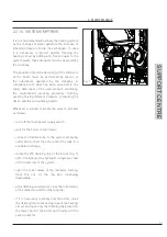
Page 53: ...th a triangle wrench pull out the front panel To intervene on the side panels of the boiler proceed as follows remove the fastening screws 2 placed laterally to the ABS cover and pull it out remove the fastening screws 3 placed on the bottom side of the boiler and remove the bottom cover remove the fastening screws 4 placed in the front edge of the side panel grasp the base of the panel and after ...

Page 54: ...ections of the master electronic board please proceed as follows DANGER Cut off the voltage from the main switch Grab at the same time the support brackets of the control panel fig 1 loosening them and turn the panel downwards unscrew the four fastening screws 1 fig 1 remove the crankcase pulling it upwards 1 1 1 1 fig 1 ...

Page 55: ...ave electronic board please proceed as follows DANGER Cut off the voltage from the main switch Grab at the same time the support brackets of the control panel fig 1 loosening them and turn the panel downwards unscrew the two fastening screws 1 fig 1 release the four hooks 2 fig 1 remove the crankcase pulling it upwards 1 2 2 2 1 2 fig 1 ...

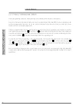
Page 56: ... different products protecting the device and the surrounding objects Whenever you need to empty the system proceed as follows turn off the main power supply switch wait for the boiler to cool down connect a flexible tube to the system emptying outlet and connect the other end of the tube to a suitable discharge rotate the RS draining tap of the boiler fig 1 and if installed of the hydraulic compr...

Page 57: ... the first fault the display will show the next alternating signalling code of the temperature of the collector In order to manually reset the unit press the RESET key when the display shows the signalling code To view the last 5 fault signalling codes chronologically starting with the most recent one activate the OFF mode by pressing the FUNCTION key and hold the key INFO for 5 seconds Use keys a...

Page 58: ...E GAS VALVE ONLY FOR GPL BOILER CHECK THE MAXIMUM ADJUSTMENT PRESSURE WITH FLAME LIGHT UP NEUTRAL AND PHASE INVERTED POWER SUPPLY PROPERLY CONNECT THE POWER SUPPLY DETECTION ELECTRODE BROKEN REPLACE IT DETECTION ELECTRODE CABLE DISCONNECTED CHECK THE WIRING ELECTRICAL CURRENT PHASE PHASE IF THE TENSION MEASURES BETWEEN NEUTRAL AND GROUND IS ALMOST EQUAL TO THE ONE MEASURED BETWEEN PHASE AND GROUND...

Page 59: ...WITCH CABLE DISCONNECTED CHECK THE WIRING WATER PRESSURE SWITCH BROKEN REPLACE IT E05 HEATING PROBE BROKEN OR INCORRECTLY CALIBRATED PROBE RESISTANCE VALUE 10 KOHM AT 25 C NTC REPLACE IT AUTOMATIC DISCONNECTED OR WET PROBE CONNECTOR CHECK THE WIRING E06 DOMESTIC CIRCUIT PROBE BROKEN OR INCORRECTLY CALIBRATED PROBE RESISTANCE VALUE 10 KOHM AT 25 C NTC REPLACE IT AUTOMATIC DISCONNECTED OR WET PROBE ...

Page 60: ...ULATOR BROKEN OR DIRTY IMPELLER CLEAN THE IMPELLER OR REPLACE THE CIRCULATOR E21 GENERAL INTERNAL BOARD ERROR INCORRECT SIGNAL RECOGNITION BY THE MODULATION BOARD MICRO PROCESSOR IF THE MODULATION BOARD DOES NOT RESET THE ERROR AUTOMATICALLY REPLACE IT AUTOMATIC E22 P A R A M E T E R S PROGRAMMING REQUEST MICRO PROCESSOR MEMORY LOSS PARAMETERS REPROGRAMMING MANUAL RESET CUT OFF THE TENSION E31 SOL...

Page 61: ... SUPPLY VOLTAGE FALLS BACK WITHIN THE REQUESTED LIMITS AUTOMATIC E52 COMMUNICATION FAULT BETWEEN MODBUS CONTROLLER AND MODBUS CONTROL UNIT NO ELECTRICAL CONNECTION CHECK THE WIRING AUTOMATIC MODBUS CONTROL UNIT BROKEN REPLACE IT E78 COLLECTOR PROBE BROKEN OR INCORRECTLY CALIBRATED PROBE RESISTANCE VALUE 10 KOHM AT 25 C NTC REPLACE IT AUTOMATIC DISCONNECTED OR WET PROBE CONNECTOR CHECK THE WIRING E...

Page 62: ...IVERTER VALVE SET TO WINTER MODE IT DEACTIVATES WHEN IT REACHES A TEMPERATURE OF 30 C OF THE DELIVERY WATER AND IF THE RETURN PROBE IS MOUNTED WHEN IT REACHES A RETURN TEMPERATURE OF 20 C F09 DOMESTIC ANTI FREEZE IT ACTIVATES AUTOMATICALLY WHEN THE DOMESTIC PROBE DETECTS A TEMPERATURE OF 4 C THE BOILER OPERATES AT MINIMUM GAS PRESSURE WITH THE DIVERTER VALVE SET TO SUMMER MODE IT DEACTIVATES WHEN ...

Page 63: ...For the 25 kW Master unit the venturi s body is code 30 00166 for Natural gas code 30 00169 for Universal LPG For the 50 kW Slave unit the venturi s body is code 30 00225 for Natural gas code 30 00226 for Universal LPG and make sure the tooth D fig 3 is adjusted downwards on the aluminium ring nut see fig 3 remount the components following the demounting operations in reverse making sure that gask...

Reviews: