background image

A Menu Structure

FLUXUS ADM 8027, F801, ADM 8127B

UMFLUXUS_F8V4-6-1EN, 2018-10-10

135

A

Menu Structure

INIT-resis-

tant

Program branch 

Parameter

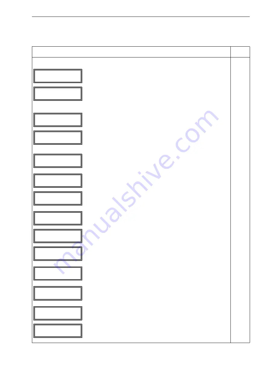
main menu: selection of the program branch 

Parameter

selection of a measuring channel (A, B) or of a calculation channel (Y, Z)
This display will not be indicated if the transmitter has only one measuring
channel.

When a measuring channel is selected (A, B)

input of the outer pipe diameter

input of the pipe circumference
This display will only be indicated if 

Special Funct.\SYSTEM set-

tings\Dialogs/Menus\Pipe Circumfer.

 is activated and 

Outer Di-

ameter

 = 

0

 has been entered.

input of the pipe wall thickness
range: depends on the connected transducers
default: 3 mm

selection of the pipe material

input of the sound speed of the pipe material
range: 600…6553.5 m/s
This display will only be indicated if 

Other Material

 is selected.

selection whether the pipe is lined

selection of the lining material
This display will only be indicated if 

Lining

 = 

yes

 is selected.

input of the sound speed of the lining material
range: 600…6553.5 m/s
This display will only be indicated if 

Other Material

 is selected.

input of the liner thickness
range: 0...50 mm
default: 3 mm

input of the roughness of the inner pipe wall
range: 0…5 mm
default: 0.1 mm (for steel as pipe material)

selection of the fluid

input of the average sound speed of the fluid
range: 500...3500 m/s
This display will only be indicated if 

Other Medium

is selected.

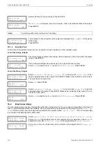
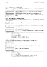
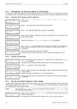
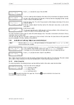
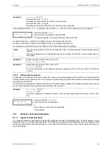
>PAR< mea opt sf
Parameter

Parameter

for Channel

A:

Outer Diameter

100.0

mm

Pipe Circumfer.

314.2

mm

Wall Thickness

3.0

mm

Pipe Material

Carbon Steel

c-Material

3230.0

m/s

Lining
 no

>YES<

Lining

Bitumen

c-Material

3200.0

m/s

Liner Thickness

3.0

mm

Roughness

0.4

mm

Medium

Water

c-Medium
 1500.0m/s

Summary of Contents for 990735-1

Page 1: ...User Manual UMFLUXUS_F8V4 6 1EN Ultrasonic Flowmeter for Liquids in Explosive Atmospheres FLUXUS ADM 8027 FLUXUS F801 FLUXUS ADM 8127B...

Page 2: ...xberger Stra e 4 12681 Berlin Germany Tel 49 30 936 67 660 Fax 49 30 936 67 680 E mail flexim flexim de www flexim com User manual for FLUXUS ADM 8027 F801 ADM 8127B UMFLUXUS_F8V4 6 1EN 2018 10 10 Cop...

Page 3: ...e Abschnitt 10 5 The transmitter can be operated in the language of your choice see section 10 5 Il est possible de s lectionner la langue utilis e par le transmetteur l cran voir section 10 5 El caud...

Page 4: ...FLUXUS ADM 8027 F801 ADM 8127B UMFLUXUS_F8V4 6 1EN 2018 10 10...

Page 5: ...FLUXUS ADM 8027 25 6 1 Location 25 6 2 Opening and Closing the Housing 25 6 3 Installation 25 6 4 Connection of the Transmitter 25 6 5 Connection of the Transducers 27 6 6 Connection of the Power Supp...

Page 6: ...g the Measurement 82 12 Displaying the Measured Values 83 12 1 Selection of the Physical Quantity and of the Unit of Measurement 83 12 2 Toggling between the Channels 83 12 3 Adjustment of the Display...

Page 7: ...Value 120 17 11 Display During the Measurement 120 18 Outputs 121 18 1 Installation of an Output 121 18 2 Error Value Delay 124 18 3 Activation of an Analog Output 125 18 4 Configuration of a Frequen...

Page 8: ...FLUXUS ADM 8027 F801 ADM 8127B Content 8 UMFLUXUS_F8V4 6 1EN 2018 10 10...

Page 9: ...term specified in the sales contract provid ed the measuring instrument is used for the purpose for which it was designed and operated according to the instructions given in this user manual Improper...

Page 10: ...asuring instrument it is important to pay special attention to the instructions given in this user manual particularly to the following points Protect the transmitter from shocks The housing may only...

Page 11: ...r an optimal measurement the flow profile has to be fully developed and axisymmetrical The shape of the flow profile depends on whether the flow is laminar or turbulent and is influenced by the condit...

Page 12: ...rection factor is recalculated by the transmitter for each new measurement Volumetric flow rate v A The volume of the fluid that passes through the pipe per unit time The volumetric flow rate is calcu...

Page 13: ...sit time difference t transducer emitter flow direction of the fluid sound path without flow sound path with flow pipe wall c c c c transducer receiver reduction in distance in the transducer flow dir...

Page 14: ...nce covered by the particle in the time between the two measuring signals and therefore to the velocity at which the particle moves through the pipe see Fig 3 5 The average value of all measured veloc...

Page 15: ...nt is conducted in the reflection arrangement see Fig 3 7 Beam The path covered by the ultrasonic signal between the transducers the transducer emitting the ultrasonic signal and the transducer receiv...

Page 16: ...lane diagonal arrangement with 1 beam reflection arrangement with 1 beam 1 transducer pair 1 sound path 1 beam 1 plane 1 transducer pair 2 sound paths 1 beam 1 plane diagonal arrangement with 2 beam r...

Page 17: ...he connection of the transducers are in the lower housing the terminals for the connection of the out puts and of the power supply on the back side of the upper housing see Fig 4 1 4 2 FLUXUS F801 ADM...

Page 18: ...asurement by inadvertently pressing key BRK Tab 4 2 Navigation scroll to the right or up through a scroll list scroll to the left or down through a scroll list Tab 4 3 Input of digits move the cursor...

Page 19: ...the operating temperature range of the sensors see Technical Specification Select the location of the transmitter within the range of the cable of the measuring point The ambient temperature at the m...

Page 20: ...propagate in the pipe horizontally By doing this the solid on the bottom of the pipe or gas bubbles in the pipe s upper part are prevented from influencing the propagation of the signal correct disadv...

Page 21: ...sources Only then it can be assumed that the flow profile in the pipe is fully developed However measuring results can be obtained even if the recommended distance to disturbance sources cannot be ob...

Page 22: ...bance source diffuser supply line l 30 D return line l 5 D disturbance source valve supply line l 40 D return line l 10 D disturbance source reducer supply line l 10 D return line l 5 D disturbance so...

Page 23: ...sound speed range compared to the diagonal arrangement transverse flow effects are compensated for because the beam crosses the pipe in 2 directions higher accuracy of measurement because the accurac...

Page 24: ...of 90 45 to the elbow plane With measurements in both directions With measurements in the reflection arrangement with 2 beams and 2 planes The sound beam plane see section 3 3 1 is selected according...

Page 25: ...he upper housing to the instrument mounting plate 3 see Fig 6 1 Fix the transmitter to the wall 6 3 2 Pipe Installation Installation on a 2 pipe Fix the pipe mounting plate 2 to the pipe see Fig 6 1 F...

Page 26: ...asuring channel B transducers measuring channel A equipotential bonding terminal lower housing equipotential bonding terminal upper housing power supply 15 14 13 12 11 10 9 8 7 6 5 4 3 2 1 PE N L L1 L...

Page 27: ...on cable through the cap nut the compression part and the basic part of the cable gland Prepare the extension cable Press the cap nut with the compression part on the cable until the thin rim of the c...

Page 28: ...s nearby the extension cable If earthing on the same potential cannot be ensured see section 6 5 2 2 Remove the left blind plug for the connection of extension cable see Fig 6 7 Open the cable gland o...

Page 29: ...7 and Tab 6 2 Fig 6 7 Connection of the extension and transducer cable to the junction box JB01 Attention For good high frequency shielding it is important to ensure good electrical contact between th...

Page 30: ...of the extension cable The compression part remains in the cap nut Push the extension cable through the cap nut the compression part and the basic part Tab 6 3 Terminal assignment transducer cable te...

Page 31: ...sing Screw the gasket ring side of the basic part into the upper housing of the transmitter Fix the cable gland by screwing the cap nut onto the basic part see Fig 6 9 Connect the leads to the termina...

Page 32: ...Fig 6 10 Fig 6 3 and Tab 6 7 Fig 6 9 Cable gland Fig 6 10 Terminals for the connection of the power supply and the outputs Tab 6 6 Connection of the power supply AC DC terminal connection terminal con...

Page 33: ...I1 I2 1 3 I1 I2 2 4 Uext 4 26 4 V Uext 0 021 A Rext 4 V example Uext 12 V Rext 0 380 current during transmitter error Ifault 0 mA HART mode I1 1 I1 2 Uext 10 24 V current during transmitter error Ifa...

Page 34: ...8027 ADM 8027L ADM 8027P ADM 8027LP B1 B4 6 8 10 12 B1 B4 5 7 9 11 Uext 5 24 V Rc k Uext Ic mA Ic 1 4 mA binary output Reed relay ADM 8027 ADM 8027L ADM 8027P ADM 8027LP B3 B4 9 11 B3 B4 10 12 Umax 4...

Page 35: ...binary output see chapter 18 Recommended configuration of the alarm output If the transmitter is disconnected from the power supply the binary output indicates an alarm state Tab 7 Circuit of the curr...

Page 36: ...sion see chapter 14 6 9 Sensor Module SENSPROM The sensor module contains important transducer data for the operation of the transmitter with the transducers It is con nected to the connector strips a...

Page 37: ...w is tightened 7 3 Installation 7 3 1 Wall Installation Fix the instrument mounting plate 2 to the wall with the 4 screws 4 see Fig 7 1 Fix the transmitter to the instrument mounting plate 2 with the...

Page 38: ...nal transducer measuring channel B transducer measuring channel A power supply outputs AV AVS ARS AR BVS BRS BR BV PE N L L1 L 1 2 3 4 6 7 8 5 9 10 11 12 14 15 13 FLUXUS F801 A10 AA F801 A10 AP AV AVS...

Page 39: ...d of the transducer cable and brush it back Insert the end of the extension cable into the housing Screw the gasket ring side of the basic part into the housing Fix the cable gland by screwing the cap...

Page 40: ...ion 7 5 2 2 Remove the left blind plug for the connection of extension cable see Fig 7 6 Open the cable gland of the extension cable The compression part remains in the cap nut Push the extension cabl...

Page 41: ...ation currents can flow to the transmitter via the extension cables Remove the left blind plug for the connection of extension cable see Fig 7 7 Open the cable gland of the extension cable The compres...

Page 42: ...able to the terminals of the transmitter see Fig 7 7 and Tab 7 4 Fig 7 7 Connection of the extension and transducer cable to the junction box JB01 Attention The external shield of the extension cable...

Page 43: ...and Tab 7 6 Tab 7 5 Terminal assignment transducer cable terminal connection V transducer core VS transducer shield RS transducer shield R transducer core Attention Observe the Safety Instructions for...

Page 44: ...tion of the power supply AC DC terminal connection terminal connection PE earth PE earth N neutral L DC L1 Phase 100 240 V AC L DC Attention Observe the Safety Instructions for the Use in Explosive At...

Page 45: ...xt 8 2 V Rc 1 k DIN EN 60947 5 6 NAMUR binary output open collector F801 A10 FF B1 6 B1 5 Uext 5 30 V Rc k Uext Ic mA Ic 2 100 mA Ioff 0 8 mA binary output open collector F801 A10 A F801 A10 P B1 B4 6...

Page 46: ...85 F801 A10 A F801 A10 P 14 A 13 B 120 termination resistor shield 15 Tab 8 Circuit of the current output Ex ib output transmitter external circuit remark internal circuit connection passive current l...

Page 47: ...nd to the serial interface of the PC If the RS232 cable cannot be connected to the PC use the RS232 USB adapter The RS232 adapter the RS232 cable and the RS232 USB adapter are part of the serial data...

Page 48: ...ansmitter If transducers are replaced or added the sensor module also has to be replaced or added Insert the sensor module into the socket of the measuring channel to which new transducers have to be...

Page 49: ...nk screw which has to be unscrewed before the housing can be opened After the installation make sure that the housing is closed correctly and that the countersunk screw is tightened 8 3 Installation 8...

Page 50: ...ightly screwed to the housing Fig 8 2 Connections of the Transmitter Fig 8 3 Terminal designation of the transmitter Attention Observe the Safety Instructions for the Use in Explosive Atmosphere see d...

Page 51: ...and body 8 with the clamp by firmly tightening the screws of the clamp Fix the cable protection hose 1 at the cable gland for mines with the hose clamp 4 by tightening the screws firmly see Fig 8 4 In...

Page 52: ...internal shield shield marked cable and unmarked shield external shield Fig 8 6 Connection of the transducers for mines to the transmitter AR 2 Schirm Schirm 3 13 14 AV AVS ARS PE L L equipotential b...

Page 53: ...7 Fix the screwed socket 2 and the gland body 4 with the clamp by firmly tightening the screws of the clamp Connect the leads to the terminals of the transmitter see Fig 8 3 Fig 8 8 and Tab 8 2 Atten...

Page 54: ...25 9 12 for cable diameters 9 12 mm M25 14 16 for cable diameters 14 16 mm Prepare the output cable with the cable gland for mines Remove as little of the insulation as possible when stripping the cab...

Page 55: ...asuring channel to which new transducers have to be connected Tab 8 4 Circuits of the outputs output transmitter external circuit remark internal circuit connection binary output open collector B1 14...

Page 56: ...how in opposite directions The transducer distance is the distance between the inner edges of the transducers see section 3 3 and Fig 9 1 and for the transducers for mines the distance between the mar...

Page 57: ...t only one transducer mounting fixture has to be mounted see Tab 9 1 Fig 9 4 Transducer mounting fixture Variofix L diagonal arrangement Fig 9 5 Scope of delivery Note When measuring in diagonal arran...

Page 58: ...n straps to length pipe circumference at least 120 mm Ratchet clasp Cut the tension strap to length pipe circumference at least 120 mm Insert approx 100 mm of the tension strap into parts 1 and 2 of t...

Page 59: ...und the pipe and insert it into the clasp see Fig 9 13 Tighten the tension strap Tighten the screw of the clasp Quick release clasp Insert the tension strap into the tension strap clamp and the metal...

Page 60: ...p on the pipe see Fig 9 10 On a horizontal pipe mount the tension strap clamp on the side of the pipe if possible Mount the metal spring on the opposite side of the tension strap clamp if necessary Pl...

Page 61: ...d to the supplied clasp Band clamp clasp Insert the tension strap into tension strap clamp 1 see Fig 9 20 Place the tension strap around the pipe and insert it into the clasp see Fig 9 21 Tighten the...

Page 62: ...outer pipe diameter 80 mm or on pipes that are not subjected to significant temperature fluctuations Position the clasp the metal spring if necessary and tension strap clamp 1 on the pipe Mount the m...

Page 63: ...9 26 Fig 9 23 Tension strap with the metal spring and the tension strap clamp Fig 9 24 Ratchet clasp with tension strap Fig 9 25 Ratchet clasp with tension strap Note To release the screw and the ten...

Page 64: ...hanical strain see Fig 9 28 Put coupling foil or some coupling compound for a short term installation on the contact surface of the transducers The coupling foil can be fixed to the contact surface wi...

Page 65: ...ne transducer mounting fixture is described transducers in reflection arrangement Overview of the mounting steps step 1 disassemble the transducer mounting fixture Variofix C step 2 mount the tension...

Page 66: ...nstallation of the rail without a clasp Cut the tension strap to length pipe circumference at least 120 mm Insert approx 100 mm of the tension strap into one of the slots of the tension strap clamp an...

Page 67: ...strap and bend it Bend both ends of the tension strap see Fig 9 37 b Repeat the steps for the second tension strap Position the tension strap at the distance s see Fig 9 37 Put the rail on the tension...

Page 68: ...o significant temperature fluctuations Place the tension strap around the pipe see Fig 9 41 Position the metal spring if mounted the ratchet clasp and the tension strap clamp On a horizontal pipe moun...

Page 69: ...en the screws Fig 9 41 Tension strap with the metal spring the ratchet clasp and the tension strap clamp on the pipe Fig 9 42 Ratchet clasp with tension strap Fig 9 43 Ratchet clasp with tension strap...

Page 70: ...ening the tensioning screws slightly The end of the screw has to be placed above the hole in the transducer see Fig 9 45 Correct the transducer distance if necessary see section 11 6 1 and section 11...

Page 71: ...f the tension strap into the slot of part 1 of the clasp see Fig 9 49 Bend the end of the tension strap back Insert the tension strap into the metal spring Insert the other end of the tension strap in...

Page 72: ...ENTER As soon as the transmitter is connected to the power supply the serial number of the trans mitter is displayed for a short time It is not possible to enter any data while the serial number is d...

Page 73: ...below For a detailed overview of the menu structure see annex A SYSTEM settings contains the following menu items set clock libraries dialogs and menus measurement outputs storing signal snap network...

Page 74: ...ss key to scroll and select a list item in the upper line Press key to scroll and select a value for the selected list item in the lower line Press ENTER function HotCode see section deactivation lang...

Page 75: ...erruption of the Power Supply As soon as the measurement begins all current measuring parameters will be stored in a non volatile INIT resistant EPROM The measurement will be interrupted if the power...

Page 76: ...fety Instructions for the Use in Explosive Atmosphere see document SIFLUXUS Note During the parameter input the transducers have to be connected to the transmitter Note The parameters will only be sto...

Page 77: ...of the fluid temperature will be displayed directly see section 11 2 4 Enter the sound speed of the pipe material Press ENTER Note Enter the sound speed of the material i e longitudinal or transversa...

Page 78: ...is used for the interpolation of the density and viscosity of the fluid 11 2 5 Fluid Pressure The fluid pressure is used for the interpolation of the sound speed Enter the average sound speed of the...

Page 79: ...e used FLEXIM cannot guarantee for the precision of the mea sured values A measurement might even be impossible If Special Version is selected enter the 6 transducer parameters specified by the manufa...

Page 80: ...Reflec reflection arrangement Diagon diagonal arrangement Note The accuracy of the recommended transducer distance depends on the accuracy of the entered pipe and fluid parameters If the displayed tr...

Page 81: ...een entered in the program branch Parameter and the transducer dis tance has been optimized afterwards as described in section 11 6 2 it is recommended to write down the sound speed for the next measu...

Page 82: ...t of measurement of the volumetric flow rate is m h For the selection of the values to be displayed and for the setting of the output options see chapter 12 For more measuring functions see chapter 13...

Page 83: ...channels HumanMux mode The command Mux Auto Human toggles between the modes see section 13 1 12 2 1 AutoMux Mode In the AutoMux mode the display and the measuring process are synchronized The channel...

Page 84: ...play This does not affect totalizing transmission of the measured values etc The following information can be displayed in the upper line The measured values of the physical quantity selected in the p...

Page 85: ...ound speed is calculated on the basis of the fluid parameters fluid selected in the program branch Parameter tem perature dependence pressure dependence ok is equal to the expected value 20 of the exp...

Page 86: ...point can be determined There are two flow totalizers one for the positive flow direction one for the negative flow direction The unit of measure ment used for totalization corresponds to the volume o...

Page 87: ...totalizers can be reset to zero manually Press key to scroll through the upper line and display the totalizers The totalizer value will be displayed in the upper line here the volume which has passed...

Page 88: ...e is enabled If the automatic toggling between the TransitTime and the NoiseTrek mode is activated the toggling parameters have to be configured Enter the time after which the transmitter has to toggl...

Page 89: ...sign and user are selected two values will have to be entered If Cut off Flow absolut and user is selected only one value will have to be entered Enter 0 zero to switch off the checking for outliers...

Page 90: ...de Select normal to display and output the flow velocity with profile correction Select uncorr to display the flow velocity without profile correction Press ENTER If uncorr is selected it has to be co...

Page 91: ...t be attenuated The damping factor has to be set separately for each of the two measuring channels Two cut off flow values for each calculation channel can be defined The cut off flow is not based on...

Page 92: ...ation channel will be invalid This message will be displayed after the parameterization of the calculation channel if the calculation function n is selected The measured values of the calculation chan...

Page 93: ...alculation channels are activated or deactivated in the same way as the measuring channels Press ENTER If a measuring channel that is needed for an activated calculation channel is not activated a war...

Page 94: ...there is an intervention in the measurement a command or key BRK 13 12 1 Defining a Program Code A program code will remain valid as long as no other valid program code is entered or the program code...

Page 95: ...TER If the entered program code is not valid an error message will be displayed for a few sec onds If the entered program code is valid the measurement will be stopped To execute a command it is suffi...

Page 96: ...sured value will be signalized acoustically This signal can be de activated see section 14 1 3 in Acoustic Signal 14 1 1 Activation Deactivation of the Data Logger 14 1 2 Setting the Storage Rate The...

Page 97: ...13 3 Select the moment at which the storing has to start Promptly The storing starts immediately On full 5 min The storing starts in the next full 5 minutes On full 10 min The storing starts in the ne...

Page 98: ...data logger memory can be dis played If on is selected and the data logger is activated the amplitude of the measured signal will be stored together with the measured values Press ENTER If on is sele...

Page 99: ...and the serial number of the transmitter is displayed in the upper line The available data logger memory will be displayed in the lower line here 18 327 addition al measured values can be stored Pres...

Page 100: ...the PC Select the character to be used to separate columns semicolon or tabulator Press EN TER Enter HotCode 232 0 see section 10 4 Set the transmission parameters in the 4 scroll lists Press ENTER b...

Page 101: ...ta to a Terminal Program Start the terminal program Enter the transmission parameters into the terminal program see section 14 2 4 The transmission parameters of the terminal program and the transmitt...

Page 102: ...Program Start the program FluxData V3 0 or higher on the PC Select the menu Options Serial interface Select the serial interface used from the PC e g COM1 Click Protocol Click OK Enter the transmissio...

Page 103: ...easured values to be stored Click OK Select the path on which the data should be stored and enter the file name Click Save The file will be stored with the file extension flx Example DEVICE X80X XXXXX...

Page 104: ...totalizers cannot be activated for the physical quantity flow velocity these columns will not be generated Offline Transmission of Data During the offline transmission of data columns will only be cre...

Page 105: ...memory can be divided into parts for the following material data material parameters transversal and longitudinal sound speed typical roughness fluid parameters min and max sound speed kinematic visco...

Page 106: ...ess ENTER Select Special Funct Install Material or Install Medium Press ENTER This error message will be displayed if the coefficient memory does not contain an area for user defined materials fluids...

Page 107: ...polation functions should be used Contact FLEXIM to find the best solution for the measuring task Select auto or user Press ENTER auto The area around the average sound speed is defined by the transmi...

Page 108: ...his error message will be displayed if the coefficient memory does not contain an area for user defined materials fluids Partition the coefficient memory accordingly see section 15 1 Select the functi...

Page 109: ...rameters or no to quit the menu item without storing Press ENTER Select yes to store the entered properties no to quit the menu item without storing Press ENTER Select delete Press ENTER Select the ma...

Page 110: ...in the current scroll list will be displayed in the lower line Select the material fluid Press ENTER The material fluid will be added to the scroll list Note The materials fluids are displayed in the...

Page 111: ...and CLR Press ENTER The new date is displayed Select ok to confirm the date or new to set the date again Press ENTER Select Special Funct SYSTEM settings Dialogs Menus Press ENTER Note The settings w...

Page 112: ...calculations Note For documentation purposes it is useful to enter the fluid pressure even if the transmitter contains no pressure dependent characteristic curves Select 1234 if the measuring point i...

Page 113: ...g m as the unit of measurement for the density Press ENTER This display will only be indicated if lb ft has not been selected as the unit of measurement for the density Select mm s or cSt as the unit...

Page 114: ...put the flow values without flow profile correction Press ENTER For further information see section 13 7 A lower limit for the flow velocity can be entered see section 13 6 An upper limit for the flow...

Page 115: ...eset to medium contrast Select Special Funct Instrum Inform to display information about the transmit ter Press ENTER The type and the serial number of the transmitter is displayed in the upper line T...

Page 116: ...s In the SuperUser mode it is possible to define some flow parameters profile bounds correction of the flow velocity for the specific application or measuring point Attention The SuperUser mode is int...

Page 117: ...the menu item SYSTEM settings For the definition of the correction of the flow velocity see section 17 3 2 Example profile bound for the laminar flow 1 500 profile bound for the turbulent flow 2 500...

Page 118: ...t is started If the transmitter is switched off without starting a measurement the entered correction data will be lost Attention The correction of the flow velocity is still active after the deactiva...

Page 119: ...x value of the totalizer is reduced with the number of decimal places For setting the behavior of the totalizers after reaching the max value see section 13 3 1 17 8 Manual Reset of the Totalizers If...

Page 120: ...ayed 17 11 Display During the Measurement In the SuperUser mode the following parameters can be displayed during the measurement besides the normal informa tion see section 12 3 Select on to activate...

Page 121: ...lay will be indicated if the output has not been installed yet Select yes Press EN TER If the output has already been installed select no to reconfigure it or yes to uninstall the output and to return...

Page 122: ...Select a list item or other range to enter the output range manually If other range is selected enter the values Output MIN and Output MAX Press ENTER after each input This error message will be displ...

Page 123: ...annot be measured during the time interval t0 t1 see Fig 18 1 The error value will be transmitted Fig 18 1 Error output Tab 18 3 Examples for the error output list item for the error output output sig...

Page 124: ...has to be within the output range Press ENTER If the multimeter displays the entered value the output functions correctly Select yes to repeat the test no to return to SYSTEM settings Press ENTER Sel...

Page 125: ...asurement of the source item will be displayed Zero Scale Val is the measured value corresponding to the lower limit of the output range as defined in section 18 1 1 Enter the highest expected measure...

Page 126: ...the source item can be totalized a request will be in dicated whether the frequency output is to be configured as a pulse output Select yes Press ENTER Enter the upper limit of the frequency Press ENT...

Page 127: ...ocity is selected as the physical quantity The use of the pulse output is not possible in this case because integrating the flow velocity does not result in a reasonable value Enter the pulse value Th...

Page 128: ...onger true mode switching function NO Cont The alarm is energized if the switching condition is true and de energized if idle NC Cont The alarm is de energized if the switching condition is true and e...

Page 129: ...n rounded measured values This might cause an apparent switching delay when the measured value changes marginally less than 2 decimal places In this case the switching accuracy of the output is higher...

Page 130: ...ce per second to avoid humming i e fluctua tion of the measured values around the value of the switching condition An alarm output of the type NON HOLD will be activated if the switching condition is...

Page 131: ...t switching Select the menu item SHOW RELAIS STAT Select onto activate the arlarm state indica tion The alarm state indication is structured as follows Rx with x being the number of the alarm output a...

Page 132: ...wer line Track down the situations when the error is displayed Contact FLEXIM The transmitter does not react when key BRK is pressed during the measurement A program code has been defined Press key CL...

Page 133: ...of the transducers When measuring on a horizontal pipe the transducers have to be mounted on the side of the pipes A vertical pipe always has to be filled at the measuring point and the fluid should...

Page 134: ...measure at low flow velocities The entered pipe roughness is not appropriate The flow velocity of the fluid is outside the measuring range of the transducer The measuring point is not appropriate Sele...

Page 135: ...material range 600 6553 5 m s This display will only be indicated if Other Material is selected selection whether the pipe is lined selection of the lining material This display will only be indicated...

Page 136: ...splay will only be indicated if no or special transducers are connected input of the length of an extension cable When a calculation channel is selected Y Z Calculation channels are only available if...

Page 137: ...Meas Data and or Serial Output are activated input of the storage rate if Storage Rate EXTRA is selected range 1 43 200 s 12 h Current loop activation of a current output This display will only be ind...

Page 138: ...ill only be indicated for R1 if Alarm Output is activated input of the upper limit of the physical quantity to be monitored This display will only be indicated if Alarm Output is activated and MAX is...

Page 139: ...coefficient memory confirmation of the selected partition the coefficient memory is being partitioned SYSTEM settings Libraries Extended Library selection of the displays for the activation of the ext...

Page 140: ...the length x selection of the unit of measurement for the temperature x selection whether the absolute pressure pa or relative pressure pg is to be used x selection of the unit of measurement for the...

Page 141: ...has to toggle to the NoiseTrek mode if there are no valid measured values in the TransitTime mode range 0 9999 s This display will only be indicated if the automatic toggling between the Transit Time...

Page 142: ...ver of the totalizer values after the measurement re start x input of a time interval after which the transmitter has to detect a long mea surement failure if there are no valid measured values 0 the...

Page 143: ...bounds user is selected request if an additional correction of the flow velocity is to be defined on the correction data can be defined off without correction of the flow velocity This display will on...

Page 144: ...nsmis selection of the displays for the formatting of the serial transmission of mea sured values activation of the serial transmission with without blanks x selection of the decimal marker for floati...

Page 145: ...red start of the transmission of measured values This display will only be indicated if the data logger contains measured values and the transmitter is connected to a PC via a serial cable error messa...

Page 146: ...icated if the selected material already exists input of a designation for the selected material input of the constants for the transversal sound speed of the material The number of constants depends o...

Page 147: ...selection of the function for the temperature and pressure dependence of the fluid parameters selection of a user defined fluid selection whether the user defined fluid is to be edited or deleted Thi...

Page 148: ...n of the displays for the input of a program code defining a program code input of the break code program code input of the access code the first three digits of the program code After the input of Ho...

Page 149: ...r absolute bar g bar relative psi a pound per square inch absolute psi g pound per square inch relative Density unit of measurement description g cm gram per cubic centimeter kg cm kilogram per cubic...

Page 150: ...m hl s hectoliter per second hl or m Ml d Megalit d megaliter per day Ml or m bbl d barrel per day bbl bbl h barrel per hour bbl bbl m barrel per minute bbl USgpd US gal d gallon per day gal USgph US...

Page 151: ...opound per minute klb 1 lb 453 59237 g 1 t 1000 kg heat flow rate Heat quantity totalized unit of measurement description unit of measurement W Watt Wh or J kW kilowatt kWh or kJ MW megawatt MWh or MJ...

Page 152: ...D N 4 0 0 D N 5 0 0 D N 6 0 0 D N 8 0 0 D N 1 0 0 0 1 m 3 h 1 0 1 0 0 1 0 3 1 0 4 l m i n 1 0 0 1 0 1 0 3 1 0 4 1 0 5 0 1 1 l s 1 0 1 0 0 1 0 3 1 1 0 g a l m i n 1 0 0 1 0 3 1 0 4 1 0 5 1 0 0 b b l d...

Page 153: ...N 2 0 0 D N 4 0 0 D N 6 0 0 1 0 0 b b l d 1 0 3 1 0 4 1 0 5 1 0 6 1 1 0 g a l m i n 1 0 0 1 0 3 1 0 4 1 0 l m i n 1 0 0 1 0 3 1 0 4 1 0 5 1 1 0 m 3 h 1 0 0 1 0 3 1 0 4 0 1 1 l s 1 0 1 0 0 1 0 3 S t r...

Page 154: ...ns m s clong m s cflow Carbon Steel steel normal 3 230 5 930 trans Stainless Steel steel stainless 3 100 5 790 trans DUPLEX duplex steel 3 272 5 720 trans Ductile Iron ductile iron 2 650 trans Asbesto...

Page 155: ...ncrusted 1 5 3 Fluid display Explanation Sound speed m s Kinematic viscosity mm s Density g cm acetone acetone 1 190 0 4 0 7300 Ammonia NH3 ammonia NH3 1 386 0 2 0 6130 Gasoline gasoline 1 295 0 7 0 8...

Page 156: ...Freon R22 Freon 558 0 1 1 2130 Crudeoil hi API crude oil light 1 163 14 0 0 8130 Crudeoil low API crude oil heavy 1 370 639 5 0 9220 30 H2SO4 sulphuric acid 30 1 526 1 4 1 1770 80 H2SO4 sulphuric aci...

Page 157: ...9 992 2 4 179 50 1 013 1542 6 988 0 4 181 60 1 013 1551 0 983 2 4 185 70 1 013 1554 7 977 8 4 190 80 1 013 1554 4 971 8 4 197 90 1 013 1550 5 965 3 4 205 100 1 013 1543 2 958 3 4 216 120 1 985 1519 9...

Page 158: ...8027 see Fig D 1 FLUXUS F801 see Fig D 2 Flameproof enclosure If the O ring is defective or the housing does not seal anymore change it see Tab D 1 Housing with increased safety If the O ring is defe...

Page 159: ...8127B UMFLUXUS_F8V4 6 1EN 2018 10 10 159 Tab D 1 transmitter O ring item number FLUXUS ADM 8027 upper housing gasket Adalet 120 mm 990735 1 FLUXUS ADM 8027 lower housing gasket Adalet 95 mm 990735 2...

Page 160: ...technik U 0 12 15 V I 0 1 27 A C ext 15 F at L 0 0 H L ext 70 H at C 0 0 F 20 C T a 60 C transmitter FLUXUS ADM 8127B FLEXIM GmbH U i 13 2 V DC L i C i negligible 20 C T a 50 C terminal L L PE or L 2Y...

Reviews: