FLUXUS ADM 8027, F801, ADM 8127B
6 Installation of FLUXUS ADM 8027
32
UMFLUXUS_F8V4-6-1EN, 2018-10-10
6.7
Connection of the Outputs
• Remove the cable gland for the connection of the outputs (see Fig. 6.2).
• Prepare the output cable with an M20 cable gland.
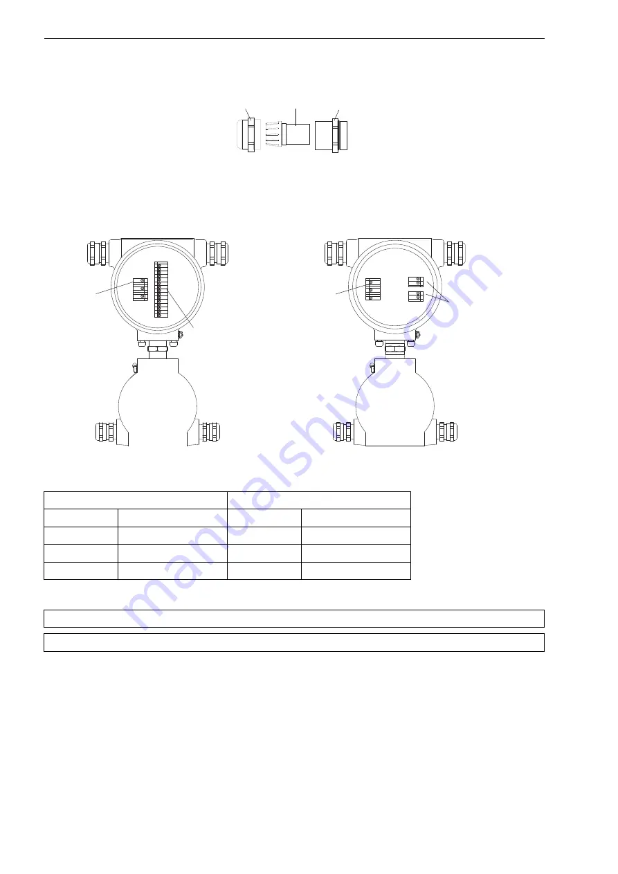
• Push the output cable through the cap nut, the compression part and the basic part of the cable gland (see Fig. 6.9).
• Insert the output cable into the upper housing.
• Screw the gasket ring side of the basic part into the upper housing.
• Fix the cable gland by screwing the cap nut onto the basic part.
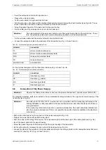
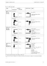
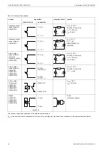
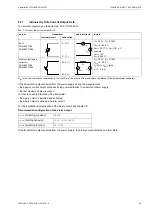
• Connect the leads of the output cable to the terminals of the transmitter (see Fig. 6.10, Fig. 6.3 and Tab. 6.7).
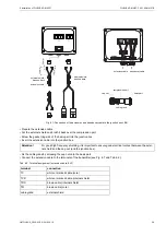
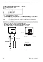
Fig. 6.9: Cable gland
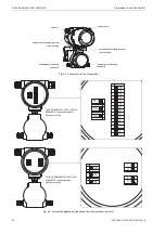
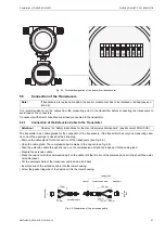
Fig. 6.10: Terminals for the connection of the power supply and the outputs
Tab. 6.6: Connection of the power supply
AC
DC
terminal
connection
terminal
connection
PE
earth
PE
earth
N
neutral
L+
+
L1
phase 100…240 V
L-
-
Attention!
Observe the "Safety Instructions for the Use in Explosive Atmosphere" (see document SIFLUXUS).
Attention!
The outputs can only be connected to a low voltage circuit (max. 30 V AC or 42 V DC against earth).
cap nut
compression part
basic part
15
14
13
12
11
10
9
8
7
6
5
4
3
2
1
1-
2+
5-
6+
PE
N/L-
L1/L+
L1(+)
N(-)
PE
FLUXUS ADM 8027C24, 8027LC24,
ADM 8027P (transmitter with frequency output):
outputs
FLUXUS ADM 8027, 8027L, 8027LP,
ADM 8027P (transmitter without frequency output):
power supply
(not intrinsically safe)
power
supply
outputs
(ADM 8027C24,8027LC24:
intrinsically safe)

