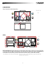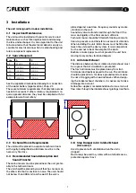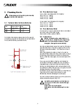
background image

8

4  electrical Works


All electrical works must be performed by an authorised electrician.

•  See the separate instructions for the automatic control and its installation.

•  See the separate wiring diagram in the unit for external connections.

•  See also Chapter 9 technical Data for more information on electrical wiring.

•  A service switch must be installed for all-pole breaking of the supply voltage to the unit. this is not included 

in the supply from FlexIt.

•  the electrical components must not be exposed to temperatures lower than -23

0

C


or higher than +55

0

C

.

4.1  Main Supply (Mains Cable)

For the L50, 3 supply cables are required, 1 for the automatic control and 2 for the electric battery (there are 2 electrical 

groups). Only 1 supply cable is required for the other units.

See the separate table in Chapter 9 Technical Data for the exact dimensions of each unit.

4.2  Connection of external Components

See the separate wiring diagram enclosed with each unit. All electrical connections must be installed by qualified 

electricians.

4.3  earth-leakage Circuit-breaker

The frequency converter must be earthed to comply with the regulations concerning high leakage 

currents (over 3.5 mA). If a line-side earth-leakage circuit-breaker is used as protection in accordance 

with the installation regulations, an earth-leakage circuit-breaker type B must be installed, which 

functions even if there are DC components. See the symbol in Fig. 9.

tighten all terminal blocks before finishing the work to avoid heat generation in the contacts, which 

may result in fire in the worst case scenario.

Fig. 9  Earth-leakage 

symbol

!

Summary of Contents for L12 X

Page 1: ...ling Unit Cross As there are various automatic control options the instructions do not contain a description of the automatic control See separate automatic control documentation 94235E 06 2009 10 Flexit L12 X L30 X L18 X L50 X L20 X ...

Page 2: ... System Drawings 10 7 Adjustment Capacity and Sound Data 11 7 1 Capacity Diagram Sound Data Specifications Flexit L12 X W E 12 7 2 Capacity Diagram Sound Data Specifications Flexit L18 X W E 13 7 3 Capacity Diagram Sound Data Specifications Flexit L20 X W E 14 7 4 Capacity Diagram Sound Data Specifications Flexit L30 X W E 15 7 5 Capacity Diagram Sound Data Specifications Flexit L50 X W E 16 8 Mai...

Page 3: ...opened and all rotating parts must have stopped Use the unit s service switch to stop the unit Units with electric heating batteries must run for 3 minutes before stopping so that the battery is cooled down Check that the doors are properly closed after service has been performed If open bosses or short duct s are used the fans must be protected with protective grids 1 1 Symbols Used This product ...

Page 4: ...orks on the jack trolley truck should correspond at least to the width of the unit 2 2 Weight Data L12 L18 L20 L30 L50 Gross unit weight 165 kg 306 kg 320 kg 360 kg 510 kg Fans 28 kg 2 fans 42 kg 2 fans 56 kg 2 fans 56 kg 2 fans 86 kg 2 fans Heat recovery system 16 kg 29 kg 29 kg 33 kg 37 kg Doors 25 kg 2 doors 91 kg 6 doors 91 kg 6 doors 91 kg 6 doors 42 kg 5 doors Net weight for transport inside...

Page 5: ... either side L18 X and L20 X With a water battery See the separate drawing on the next page for connection to the water battery common to L18 L20 and L30 The dimensions are the same on both end sides The units have 2 doors on each side and can be operated from either side L30 X With a water battery See the separate drawing on the next page for connection to the water battery common to L18 L20 and ...

Page 6: ...ery Hole templates on both sides have been prepared in the factory It is important for water pipes not to block doors or prevent the removal of the heat recovery system filters and fans The dimensions are the same on both end sides The L50 has 5 doors in front Shown here as a right model XR Also available as a left model XL Fig 6 Fig 7 1300 900 400 295 400 235 524 970 205 130 1430 2860 2800 All me...

Page 7: ...e that is sensitive to noise The unit should not be less than 400 mm from the wall If the unit is placed against a wall low frequency sound may create vibrations in the wall Sound may also be transferred through the floor if the mass and rigidity of the floor are not sufficient Technical rooms should be fitted with floating concrete floors to prevent sound transfer on account of vibration When ins...

Page 8: ...electrical groups Only 1 supply cable is required for the other units See the separate table in Chapter 9 Technical Data for the exact dimensions of each unit 4 2 Connection of External Components See the separate wiring diagram enclosed with each unit All electrical connections must be installed by qualified electricians 4 3 Earth leakage Circuit breaker The frequency converter must be earthed to...

Page 9: ...ied otherwise The water supply must be at the bottom of the water battery the return must be on the top Place the adjustment valve as close to the unit as possible Please note that many valve motors can go in both directions and this can be set on the motor Set it so that the valve opens on an increasing 0 10 V signal If you use a water battery that has not had glycol or another antifreeze added t...

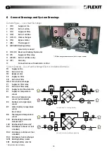
Page 10: ...atic control System Drawing Cross Heat Exchanger Electric and Water Batteries M1 Supply air fan M2 Extract air fan M3 Bypass motor FI1 Supply air filter FI2 Extract air filter HR X Cross heat exchanger P1 Supply air filter relay P2 Extract air filter relay P3 Supply air fan flow detector B1 Supply air temperature sensor B3 Extract air temperature sensor not standard B4 Outdoor air temperature sens...

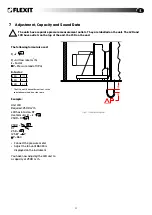
Page 11: ...Required 2500 m 3 h L30 has k factor 97 Use formula Q k P 2500 97 P 2500 97 P 97 97 25 8 P 25 8 2 P P 664 Connect the pressure meter Adjust the fan until 664 Pa is displayed on the instrument You have now adjusted the L30 unit to a capacity of 2500 m 3 h 7 Adjustment Capacity and Sound Data The units have separate pressure measurement outlets They are labelled on the unit The L20 and L30 have outl...

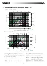
Page 12: ...us octave bands and total LwA This is read directly from the supply air table Correction factor for LwA Hz 63 125 250 500 1000 2000 4000 8000 LwA Supply air 7 1 0 3 3 13 17 28 Extract air 23 10 0 9 16 27 32 38 Radiated 30 24 23 25 26 30 32 40 21 6 Extract air side with F7 filter Power consumption in Watt Contact resistance Pa Air flow rate m3 h Pressure correction factor Power consumption in Watt ...

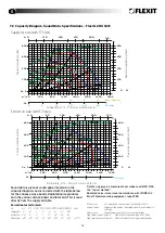
Page 13: ... total LwA This is read directly from the supply air table Correction factor for LwA Hz 63 125 250 500 1000 2000 4000 8000 LwA Supply air 6 0 3 2 4 11 16 24 Extract air 15 2 5 2 4 21 51 55 Radiated 40 40 33 31 28 29 33 44 23 7 Extract air side with F7 filter Power consumption in Watt Contact resistance Pa Air flow rate m3 h Pressure correction factor Power consumption in Watt Contact resistance Pa...

Page 14: ...octave bands Radiated noise produces Lw in the various octave bands and total LwA This is read directly from the supply air table Correction factor for LwA Hz 63 125 250 500 1000 2000 4000 8000 LwA Supply air 2 9 1 3 4 9 17 28 Extract air 20 6 7 1 17 24 34 43 Radiated 40 40 33 31 28 29 33 49 23 6 Extract air side with F7 filter Power consumption in Watt Contact resistance Pa Air flow rate m3 h Pre...

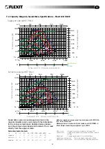
Page 15: ...ctave bands Radiated noise produces Lw in the various octave bands and total LwA This is read directly from the supply air table Correction factor for LwA Hz 63 125 250 500 1000 2000 4000 8000 LwA Supply air 1 7 0 3 4 11 19 30 Extract air 16 6 4 1 14 22 33 42 Radiated 28 34 30 26 26 28 34 47 21 7 Extract air side with F7 filter Power consumption in Watt Contact resistance Pa Air flow rate m3 h Pre...

Page 16: ...us octave bands and total LwA This is read directly from the supply air table Correction factor for LwA Hz 63 125 250 500 1000 2000 4000 8000 LwA Supply air 5 12 2 2 3 11 21 32 Extract air 17 8 0 3 12 19 30 42 Radiated 36 28 25 25 25 27 31 41 20 3 Extract air side with F7 filter Power consumption in Watt Contact resistance Pa Air flow rate m3 h Pressure correction factor Power consumption in Watt ...

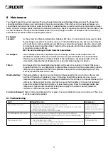
Page 17: ...n in the air that passes through the filters It is very important to replace filters to ensure that the system works properly Filters must be replaced when the filter replacement lamp on the control panel lights up They must be replaced at least once a year Heating battery The heating battery electric or water based will be exposed to dirt very rarely as the system has filters fitted with a high d...

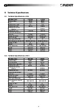
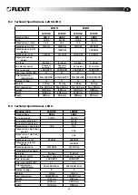
Page 18: ...165 kg Duct connection Dia 315 mm Dia 315 mm Height 1025 mm 1025 mm Width 1700 mm 1700 mm Depth 630 mm 630 mm 9 2 Technical Specifications L18 X Heating type L18 XW L18 XE Rated voltage 230 V 400 V Fuse operation 1x10 A 3x20 A Rated current operation 8 A 19 A Rated power total 1800 W 12300 W Rated power electric battery 10000 W Rated power fans 2x550 W 2x550 W Rated preheating power Fan type F whe...

Page 19: ...n Dia 400 mm Dia 400 mm Dia 400 mm Dia 400 mm Height 1400 mm 1400 mm 1400 mm 1400 mm Width 2060 mm 2060 mm 2200 mm 2200 mm Depth 900 mm 900 mm 900 mm 900 mm 9 4 Technical Specifications L50 X Heating type L50 XW L50 XE Rated voltage 400 V 400 V Fuse operation 3x20 A 3x20 A Fuse electrical group 1 3x32 A Fuse electrical group 2 3x32 A Rated current operation 16 A 16 A Rated current electrical group...

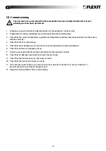
Page 20: ...ted correctly 4 Check that the fans rotate freely 5 Check that all air dampers work The unit must not be operated with closed air dampers 6 Check that all doors are properly closed 7 Start the unit as described in the documentation for the automatic control 8 Check that air dampers open and close when the unit stops 9 Check that the heat recovery system works correctly 10 Check that the heat contr...

Page 21: ...ive notice of lack of conformity applies to this product in accordance with the existing terms of sale provided that the product is used correctly and maintained Filters are consumables The symbol on the product or on its packaging indicates that this product may not be treated as household waste Instead it shall be handed over to the applicable collection point for the recycling of electrical and...

Page 22: ...22 ...

Page 23: ...23 ...

Page 24: ...Flexit AS Televeien 15 N 1870 Ørje www flexit com ...

Reviews: