Page
71
of
72
Copyright 2021 FlexRadio. All Rights Reserved.
7 June 2021(FW:0.9.12, Utility: 0.9.12)
14.2.7
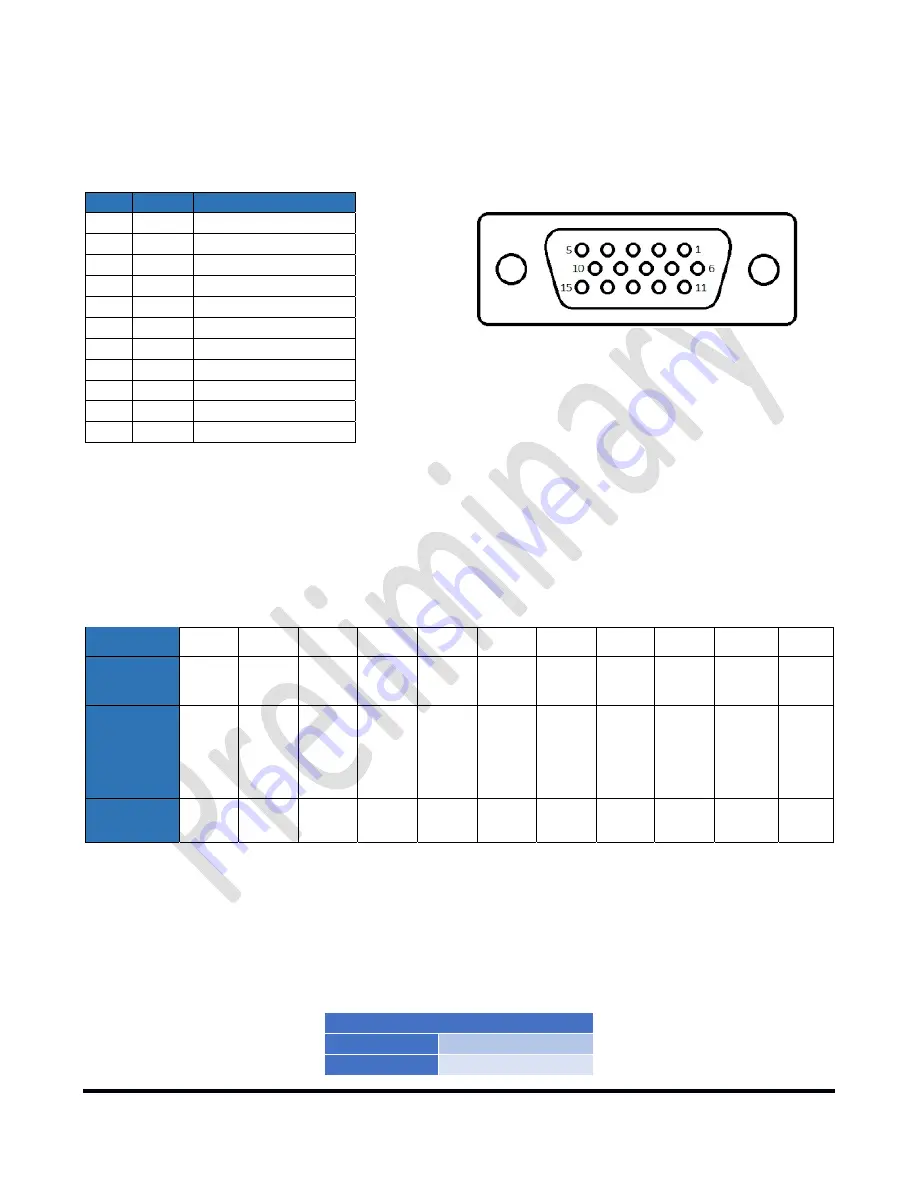
PTB/BCD Connector Pinout
PTB
input
–
When
a
5
to
15
‐
volt
DC
signal
is
applied
to
one
of
the
pins
described
in
the
following
table,
the
tuner
will
select
the
corresponding
band.
The
pins
are
opto
‐
isolated.
Pin
15
is
the
signal
ground.
Pin
Band
Frequency
1
160m
1.8
–
2.0
MHz
2
80m
3.5
–
4.0
MHz
3
40m
7.0
–
7.3
MHz
4
30m
10.10
–
10.15
MHz
5
20m
14.00
–
14.35
MHz
6
17m
18.068
–
18.168
MHz
7
15m
21.00
–
21.45
MHz
8
12m
24.89
–
24.99
MHz
9
10m
28.0
–
29.7
MHz
10
6m
50.0
–
54.0
MHz
15
Signal
Ground
i
–
The
60
‐
meter
band
cannot
be
selected
with
this
method.
BCD
input
–
A
4
‐
bit
BCD
signal
(5
to
15
‐
volt
DC)
selects
a
band.
The
pins
are
opto
‐
isolated.
Pin
15
is
the
signal
ground.
The
BCD
inputs
are
designed
for
connection
directly
to
a
band
decoder
output
provided
by
radios
such
as
Yaesu
and
Elecraft.
Band
160m
80m
40m
30m
20m
17m
15m
12m
10m
6m
None
Frequency
(MHz)
1.8
3.5
7
10
14
18
21
24
28
50
NA
Pin
11
Pin
12
Pin
13
Pin
14
H
L
L
L
L
H
L
L
H
H
L
L
L
L
H
L
H
L
H
L
L
H
H
L
H
H
H
L
L
L
L
H
H
L
L
H
L
H
L
H
L
L
L
L
Hex
Value
1
2
3
4
5
6
7
8
9
A
0
i
–
The
60
‐
meter
band
cannot
be
selected
with
this
method.
14.3 Power Derating Table
The
tuner
will
scale
maximum
allowed
power
input
based
on
the
following
schedule:
SWR
Maximum
Power
<
1.x:1
2000W
1.x:1
to
1.x:1
xxxW


