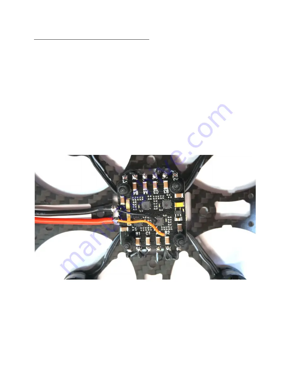
Step 3: Solder the motors and FC power leads
Carefully route the motor wires under the ESC so they wrap around the center screws and
around the bottom of the ESC. This routing method will keep the motor wires nice and neat and
will help avoid being snagged by a prop.. Confirm your measurements and trim each motor
wire.
Strip ~2mm of insulation off each motor wire and pre-tin them. Take care not to pre-tin any
wires directly over the ESC, as tiny drops of solder can land on the ESC and damage or short
the mounted components.
Once all the wires are pre-tinned, solder each wire to the appropriate pads on the ESC. Note
that the motor layout and ESC pad orientation aren’t consistently named! Specifically, motor 3
will be soldered to pads A4, B4, and C4. Motor 4 will be soldered to pads A3, B3, and C3.
Motors 1 and 2 solder to the properly numbered pads. Don’t worry about which individual
motor wire goes to which pad in the group of three, as we will set motor spin directions in the
BLHeli Suite software.
We will now attach power leads for the flight controller. Trim two pieces of 20-24 awg wire to
about 30cm and strip and tin the ends. Solder one to the positive battery lead joint and one to
the negative battery lead joint as shown in the photo. The orange wire is the positive and the
black wire is ground. Leave the other ends loose for now.
4


