4
© 2016 OJ Electronics A/S
3
2
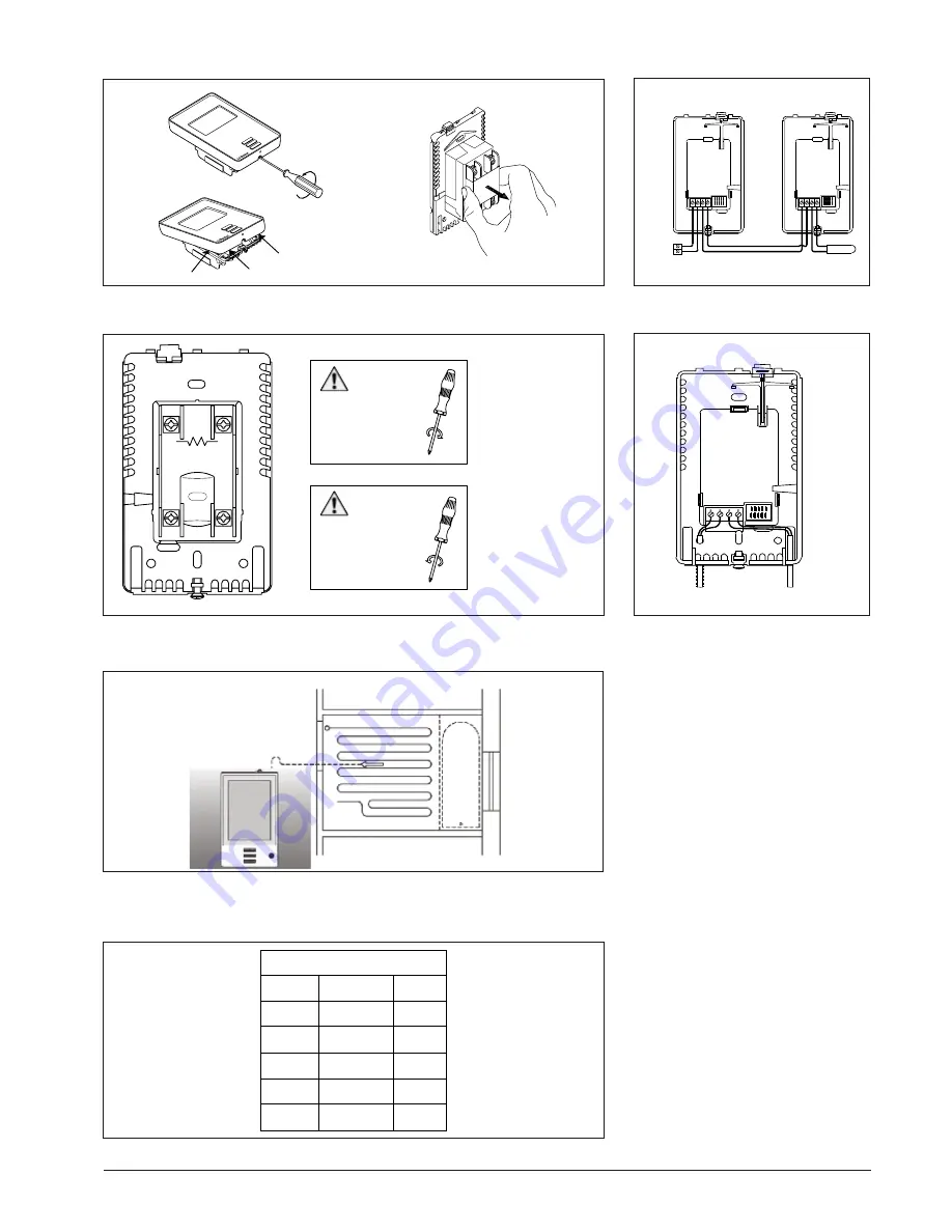
120 / 240 VA
C
L2(N)
L1(L)
LINE
1800W / 3600W MAX 15A
LOAD
1
4
BR1015A01b
© OJ Electronics A/S
Fig. 2
1
2 3 4
LOAD
1800W/3600W MAX 15A
LINE
120 / 240 VAC
L1(L) L2(N)
WARNING
When fastening the screws
do NOT exceed a torque
greater than
1.2 Nm
WARNING
When loosening the screws
do NOT detach the screws
from the terminal.
ES:
Advertencia
Al apretar los tornillos no
aplique un par de apriete
mayor que 1,2 N-m.
FR:
Avertissement
Lors du serrage des
vis, ne pas excéder un
couple de 1,2 Nm.
ES:
Advertencia
Al aflojar los tornillos, no
los separe completamente
del terminal.
FR:
Avertissement
En desserrant les vis,
ne pas les enlever
des bornes.
Fig. 3
Udarbejdet af:
Udarbejdet d.: 29.05.2015
Side 1 af 1
©
2015
OJ ELECTRONICS A/S
•
STENAGER 13B
•
DK-6400 SØNDERBORG
NTC 12k
Ω @ 25°Celsius
°Celsius
°Fahrenheit Ohm (Ω)
-10°C
14°F
55076Ω
0°C
32°F
34603Ω
10°C
50°F
22284Ω
20°C
68°F
14675Ω
30°C
86°F
9860Ω
Fig. 4
POWER MODULE
THERMOSTAT
A B C D
OUT
SENSOR
IN / SENSOR
C
D
USG - 4000
BR1015A02b
A B C D
OUT
IN / SENSOR
Fig. 5
BR1015A03a © 2015 OJ Electronics
A/S
1
A B C D
OUT
IN / SENSOR
1
2
2
UCG / UDG / UTN
Fig. 6
Fig. 1
BR1015A04a
BR1012C02a
© 2015 OJ Electronic
A/
S
BR1012C03
a
© 2015 OJ Electronic
A/
S
BR1012C02a, BR1012C03a & BR1015A05
BR1015A02b
BR1015A01b
BR1015A03a
BR928A07b
Summary of Contents for FLK30
Page 5: ...5 2016 OJ Electronics A S...
Page 6: ...6 2016 OJ Electronics A S...
Page 7: ...7 2016 OJ Electronics A S...