2
CONTENTS
Introduction
2
Applications
2
Function and Controls
2
Hazards & Risks
3
Operation
4
Customer Responsibility
5
Transporter Trolley Operation
5
Care and Preventive Maintenance
6
Troubleshooting
6
Specifications
7
Spare Parts and Service
8
INTRODUCTION
Thank you for your selection of Parchem equipment.
Parchem have specialised in the design and manufacture of quality
products since 1951.
We have taken care in the assembly and testing of this product.
Should service or spare parts be required, prompt and efficient
service is available from our branches.
General Safety Instructions for the Operation of Power Equipment
The goal of Parchem is to produce power equipment that helps
the operator work safely and efficiently. The most important safety
device for this or any tool is the operator.
Care and good judgement are the best protection against injury.
All possible hazards cannot be covered here, but we have tried
to highlight some of the important ones. Individuals should look
for and obey Caution, Warning and Danger signs placed on
equipment, and displayed in the workplace. Operators should
read and follow safety instructions packed with each product, and
complete there own JSEA Work Method Statement before use.
Learn how each machine works. Even if you have previously used
similar machines, carefully check out each machine before you use
it. Get the “feel” of it and know its capabilities, limitations, potential
hazards, how it operates, and how it stops.
APPLICATIONS
The Ride On Power Trowel can be used for trowelling concrete
surface through floating and finishing operations. Three types of
blades can be fitted with the trowel: combination, floating and
finishing blades. Two types of float pans are compatible and
available: regular dish pan and mild dish pan.
FUNCTIONS AND CONTROLS
The trowel machine reproduces the action of hand trowels while
giving a high quality dense finish with wear resistance. The angle of
the blades is adjustable during operation from a floating position,
with the full blade area in contact to flatten the surface, to a
finishing position with the blades tilted to give a finished surface.
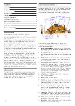
The figure above shows the location of the controls and
components for this Ride on Power Trowel. The functions of
controls are described below:
1. Handle Grip/Handle Bar
– When operating the trowel, hold
both handgrips with hands. Replace handgrips when they are
worn or damaged.
2. Blade Pitch Control
– Turn the star knob clockwise to
increase blade pitch, and counter-clockwise to decrease blade
pitch.
3. Throttle Control Lever
– Controls the speed of engine. Push
the lever downwards to increase engine speed, upwards to
decrease engine speed.
4. Safety Stop Switch or Inertia Lever
– If the operator loses
control and lets go of the trowel, the inertia lever will be swung
to OFF position by centrifugal force, and shut down the engine
or if a dead mans pedal is fitted releasing the foot pressure,
will stop the machine. These switches MUST be tested before
each use of the trowel. It is also recommended that these
switches be used to stop the engine after each use of the
trowel to validate there operation.
5. Lifting Frame
– Use the lifting frame to lift the trowel and
move to desired location.
6. Engine
– Vanguard 35HP Petrol.
7. V-belt Cover
– Safety guard for V-belts and pulleys. Remove
the cover only to get access to the V-belts for inspection and
replacement. Make sure the cover is always in place when
trowel is in operation or de isolated.
8. Gearbox
– Transfers power from engine to the spider
assembly. Check oil level in gearbox through the sight glass
on a daily basis, and refill as necessary only with machine
stopped.
9. Trowel Arm
– NEVER use broken or bent trowel arms. Check
for arm alignment if blades show uneven wear or some wear
earlier than others only when machine stopped and isolated.
10. Blades
– Combination blades, floating blades and finishing
blades can be fitted with the trowel.
11. Guard Ring
– NEVER attempt to put hands or feet inside the
guard ring while the engine is running.


