14
1300 353 986
flextool.com.au
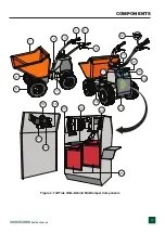
COMPONENTS
1.
Tub or Bucket
— Used for the transportation of
material. Tub holds approximately 12.0 cubic feet
(0.44 cubic yards) of water.
2.
Lifting Point
— Attach a suitable lifting strap to these
points when lifting of the Mini Dumper is required.
3.
Handle Bar
(Steering)
— This handle bar is used to
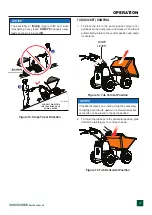
steer the Mini Dumper. When steering the Mini Dumper,
use both hands and hold onto both handle bar grips.
4.
Deadman Control Lever
—
Red
handle lever, when
engaged (closed) allows the use both to travel in either
a forward or reverse direction. Works in conjunction
with forward and reverse control levers. In addition, this
lever when engaged releases the brake.
5.
Forward/Reverse Speed Control Lever
— When fully
engaged, the Mini Dumperwill travel at
FULL
speed in
either the forward or reverse direction. When released,
the Mini Dumperwill
STOP
. This feature is only on the
electric models.
6.
Reverse Control Lever Signal Cable
— This lever/
cable is a 2-wire cable (switch) that when activated
sends a +12 VDC signal (J1-10) to the motor controller
indicating that the reverse travel function has been
selected.
7.
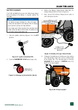
Battery Charger Cable
— Plug battery charger cable
plug into a 240 VAC power source.
8.
Tires
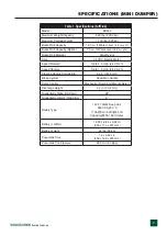
— Unit uses pneumatic tires. Reference
Table 1 for tire size.
9.
Tipping Bracket Pivot Bar
— Attach this bar to the
Mini Dumper frame to tip tub. Be sure to lock in place
(locking levers).
10.
Deadman Microswitch
— When activated sends a
+12 VDC signal (J1-3) to the motor controller to release
the brake. Microswitch is located inside handle.
11.
Dump Control Lever
o
t
d
r
a
w
r
o
f
r
e
v
e
l
e
h
t
h
s
u
P
—
place the tub in the dump position (vertical).
12.
Free-Wheel Brake Bypass Switch
— Momentary
toggle switch. Allows the Mini Dumper to be moved
with the electric motor brakes disengaged
13.
Battery/Diagnostic Gauge
— Uses a Curtis Model
3100R Gauge Display. Displays battery voltage and
fault codes. CAN bus compatible.
14.
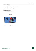
Emergency Stop Switch
— In the event of an
emergency,
push
this button to shutdown the electric
motor.
15.
Electric Motor
(
Front)
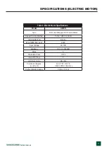
— Uses a 24 VDC, 750 watt
electric motor.
16.
Electric Motor
(
Rear)
— Uses a 24 VDC, 750 watt
electric motor.
17.
Ignition/Key
— When activated allows the unit to be
started.
18.
Contactor
— Heavy duty relay used for the switching
of the ON and OFF +12 VDC power required for
the Curtis Model 1229 motor controller. Works in
conjunction with the contactor solenoid.
19.
Fuse Box
— Provides protection for various electrical
circuits. Reference wiring diagram in the manual.
20.
Contactor Fuse
s
e
d
i
v
o
r
p
t
a
h
t
e
s
u
f
p
m
a
0
0
1
—
protection for the electric motor.
21.
Contactor Solenoid
(Coil)
— When energized (coil),
12 VDC power to transfered to the Curtis Model
1229 motor controller via the K1-1and K1-2 contacts.
22.
5K OHM Potentiometer
— Provides signal for speed
sensor.
23.
Motor Speed Controller
— Unit uses a Curtis Model
1229 Controller. Requires a 24 VDC input. Interfaces
with CAN bus applications.
24.
Battery Charger
(
Electric)
— When activated, charges
both 12-volt batteries.
25.
Battery
— Uses two 12 volt batteries connected in
series (24 volts). Always use gloves and eye protection
when handling the batteries.


