background image

30

1300 353 986  

flextool.com.au

Troub

leshooting (Er

ror Codes)

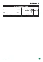
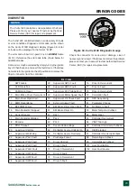
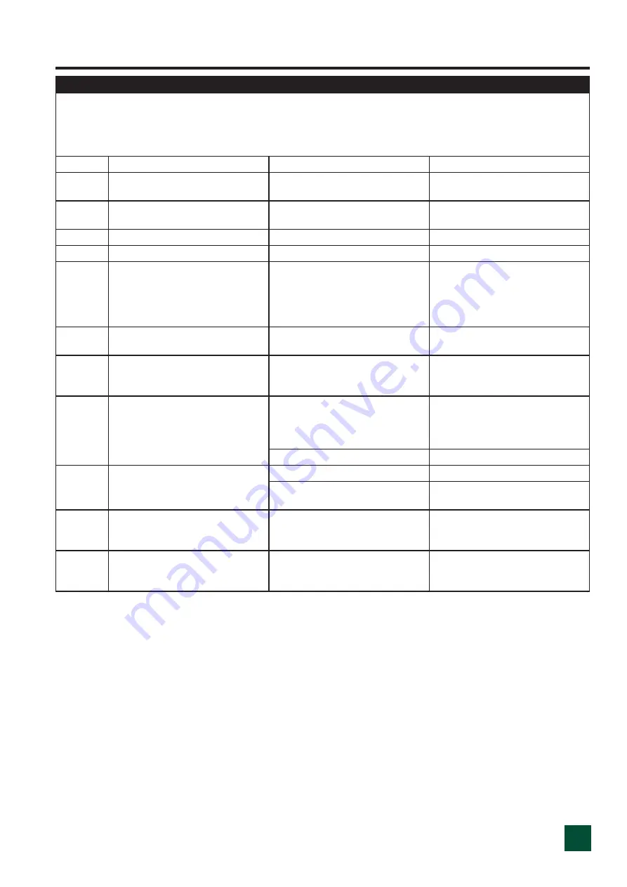
The machine controller detects a wide variety of faults or errors. Diagnostic information can be obtained on the 3100R fuel gauge display where an error code in the format 
“Err ##”. The troubleshooting chart below describes the error code faults and their possible causes. Whenever a fault is encountered the first action should be to turn off the ignition 
and push in the E-stop button. Then pull out the E-stop button and turn the ignition back on to see if the fault clears. This is the RESET procedure: If the error code does not clear 
after the machine RESET, turn off the ignition switch and remove the 35-pin connector. Check the connector for correction or damage, clean it if necessary, and reinsert it. If the 
error is still seen then the wiring and connections on the machine should be checked for breakages or loose connections. The table below should be used as a reference once the 
above checks have been carried out.
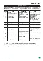
Error Code

Symptom

Possible Problem

Solution

1

HW fail-safe  
Motor fault voltage (hardware failure)

Motor voltage does not correspond to 
throttle request?

Check for short in motor or motor wiring.

10

Main brake driver over current.

Short circuit or overloaded controller 
driver?

Check brake controller driver. Reference 
Curtis controller owner's manual.

15

Main current dropped.

Main contactor failed to open?

Clean the contactor switch.

17

Main contactor welded.

Main contactor fault / failed to close?

Replace contactor.

33

Supervisor DIR check fault.

Program issue?

If fault is on an external signal, check 
that signal first. If no problem with 
the external signal, likely indicates an 
internal controller fault. Reference Curtis 
controller owner's manual

34

External supply fault.

Under voltage?

Check control wiring circuit, 
potentiometer wiring in particular.

36

EM-brake driver open drain.

Hold voltage set at 90%?

Check brake electrical connectors. 
Check continuity. Replace motor brake 
if failed.

54

Pre-charge failed/fault.

Low battery voltage?

Check battery voltage. 25V (11/12V per 
battery) is good condition, 22V (9/10V 
per battery) or lower is bad battery 
condition.

Short circuit on traction motor outputs?

80

HPD sequencing 
HPD fault present > 10 seconds.

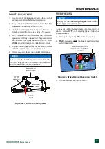
Misadjusted throttle?

Adjust. See maintenance section.

Broken throttle potentiometer or throttle 
mechanism?

Replace.

92

Traction motor open / not connected. 
Controller cannot see the motor.

Short circuit in the motor?

Check the resistance across the motor 
leads.

99

Undervoltage cutback.

Battery voltage < undervoltage 
threshold?

Check connection at battery or controller. 
Check no corrosion on the battery 
terminals.

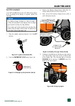
Quick checks if no reading on the fuel gauge and the machine does not operate:

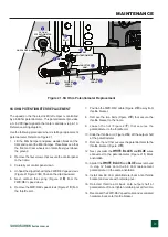
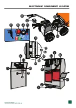
1.  Check 10-amp ignition fuse located on the backside of the control panel. Reference 'Electronic Component Locator" drawing.

2. Check 100-amp main fuse*located on the backside of the control panel. Reference 'Electronic Component Locator" drawing.

2. When changing the 100-amp fuse, ensure that the positive battery cable is fully disconnected. Electrical maintenance should be carried out 
  by a qualified person.

ERROR CODES

Summary of Contents for TUFFTRUK EB500

Page 1: ...FOR MORE INFORMATION CONTACT US ON 1300 353 986 OR VISIT flextool com au Version 1 0 November 2022 OPERATING INSTRUCTIONS FLEXTOOL TUFFTRUK EB500 ...

Page 2: ...2 1300 353 986 flextool com au This page is intentionally blank ...

Page 3: ...ty Information 4 7 Specifications Mini Dumper 8 Specifications Electric Motor 9 Noise And Vibration 10 Dimensions 11 General Information 12 Components 13 14 Inspection 15 16 Operation 17 20 Maintenance 21 27 Error Codes 29 30 Troubleshooting 31 Electronic Component Locator 33 Wiring Diagram 34 ...

Page 4: ...FETY CAUTION NEVER operate this equipment without proper protective clothing shatterproof glasses respiratory protection hearing protection steel toed boots and other protective devices required by the job or city and state regulations Avoid wearing jewelry or loose fitting clothes that may snag on the controls or moving parts as this can cause serious injury NEVER operate this equipment when not ...

Page 5: ... v o e c a f r u s e h t t c e p s n i Look for holes drop offs and obstacles Look for rough and weak spots on docks ramps or floor ALWAYS Look for oil spills wet spots and slippery surfaces Look for soft soil deep mud and standing water Watch for anything that might make you lose control or cause the TuffTruk to tip over ALWAYS clear away trash and debris Pick up anything that might puncture the ...

Page 6: ... condition Fix damage to machine and replace any broken parts immediately The entireTuffTruk tub shroud wheels etc should be cleaned after every use Make sure there is no buildup of concrete grease oil or debris on the machine ALWAYS store equipment properly when it is not being used Equipment should be stored in a clean dry location out of the reach of children and unauthorized personnel BATTERY ...

Page 7: ...NOT use the TuffTruk to transport people When transporting the TuffTruk on a truck or trailer know the overall height to avoid contacting overhead obstructions such as bridges and power lines Check the truck and ramp capacities ENVIRONMENTAL SAFETY DECOMMISSIONING NOTICE Decommissioning is a controlled process used to safely e l b a e c i v r e s r e g n o l o n s i t a h t t n e m p i u q e f o e...

Page 8: ... Speed Forward Up to 4 0 mph 6 43 km h Speed Reverse Up to 1 5 mph 2 42 km h Steering Radius Outside Dia 56 in 1422 mm Brake System Dead Man Handle Dump Control Mechanical Dump and Manual Return Discharge Height 2 0 in 50 8 mm Gradeability Slope Up Down 25 Gradeability Lateral Side Side 6 Battery Type 12V 27 AGM Deep Cell 550 CCA 0 C 77Ah 5 Hr 89Ah 20 Hr Capacity 25A 158 minutes Battery LxWxH 12 0...

Page 9: ...gnet DC Electric Motor Speed Control Method Curtis 1228 Controller Starting Method Electric Max RPM No Load 2900 Input Voltage 24 VDC Wattage 750 X 2 1500W Poles 4 Protection Class IP 44 Insulation Class F IEC Duty Cycle S3 15 Dimension Approx L x W x H 6 4 X 7 81 X 5 7 in 164 X 200 X 145 mm Dry Net Weight Approx 22 lbs 10 kg ...

Page 10: ...the operating condition of the machine that generates the most repeatable but highest values in accordance with the applicable standards for the machine 3 Per EU Directive 2002 44 EC the daily exposure action value for hand arm vibration is 2 5 m s2 A 8 The daily exposure limit value is 5 m s2 A 8 Table 3 Noise and Vibration Emissions Model EB500 Guaranteed ISO 11201 2010 Based Sound Pressure Leve...

Page 11: ...eference Letter Dimension in mm A 34 20 869 B 16 50 419 C 70 30 1 786 D 41 90 1 064 E 39 20 995 F 10 9 277 G 7 40 188 H 28 60 726 I 53 0 1 340 J 33 40 848 K 5 50 140 L 33 40 848 M 6 37 162 N 56 0 1 22 D E C A B F SIDE VIEW TOP VIEW M L J REAR VIEW K H G I OUTSIDE DIAMETER TURNING RADIUS N O ...

Page 12: ...ler ECU This controller provides functional and directional control of theTuffTruk Mini Dumper It allows the Mini Dumper to start and stop or move in a forward or This controller can detect a wide variety of faults or error conditions Diagnostic information can be obtained by interfacing with the Curtis Model 3100R Gauge Display This gauge will display error codes as referenced in the maintenance ...

Page 13: ...13 1300 353 986 flextool com au COMPONENTS 1 4 5 6 11 12 17 13 14 3 2 9 8 18 7 15 16 19 22 23 24 21 20 25 10 Figure 2 TuffTruk Walk Behind Mini Dumper Components ...

Page 14: ...or controller to release the brake Microswitch is located inside handle 11 Dump Control Lever o t d r a w r o f r e v e l e h t h s u P place the tub in the dump position vertical 12 Free Wheel Brake Bypass Switch Momentary toggle switch Allows the Mini Dumper to be moved with the electric motor brakes disengaged 13 Battery Diagnostic Gauge Uses a Curtis Model 3100R Gauge Display Displays battery ...

Page 15: ...tric source be sure to disconnect the battery cables CAUTION NEVER disable or disconnect the emergency stop switch It is provided for operator safety Injury may result if it is disabled disconnected or improperly maintained CAUTION ALWAYS disconnect the negative terminal FIRST and reconnect the negative terminal LAST INSPECTION Battery Cable Installation ALWAYS be sure the battery cables Figure 3 ...

Page 16: ...e Mini Dumper s steering turns freely and that there is no binding This section is intended to assist the operator with the initial start up of the unit It is extremely important that this section be read carefully before attempting to use theTuffTruk walk behind Mini Dumper in the field DO NOT use your Mini Dumper until the General Information and Inspection sections ofthismanualhavebeenreadandth...

Page 17: ...ler J1 3 to release the brake 2 230v 110v 50Hz 60Hz 1 EMERGENCY STOP SWITCH 2 230v 110v 50Hz 60Hz 1 IGNITION SWITCH BATTERY GAUGE LOW BATTERY LEVEL DIAGNOSTIC GAUGE Figure 7 Deadman Lever 4 Slightly squeeze the forward reverse speed control lever Figure 8 until the Mini Dumper begins to move in a forward direction Figure 8 Forward Reverse Speed Control Lever Electric 5 On the opposite side of the ...

Page 18: ...to determine the grade of the path The EB500 Mini Dumper can travel up or down slopes not exceeding 25 Figure 12 DO NOT travel on steeper slopes To determine the grade of your path of travel use the formula and graph in Figure 12 2 Lateral side to side travel cannot exceed 6 Figure 12 Determining Grade of Slope CAUTION DO NOT steer the Mini Dumper left or right when traveling upor down on a grade ...

Page 19: ... 1 To place the tub in the dump position Figure 14 pull back on the dump lever and release The tub will automatically rotate to the vertical position and dump its contents Figure 14 Tub Vertical Position 2 To return the tub back to the horizontal position grab hold of the tub Figure 15 and push down Figure 15 Tub Horizontal Position DUMP LEVER NOTICE If the Mini Dumper is on a incline it might be ...

Page 20: ... lever and come to a complete stop Brake is now set 2 Place the ignition switch in the OFF position 3 Block wheels if on a slope or incline EMERGENCY SHUTDOWN 1 Push the EMERGENCY STOP switch Figure 16 Figure 16 Emergency Stop Switch Push 2 230v 110v 50Hz 60Hz 1 EMERGENCY STOP SWITCH ...

Page 21: ...5 Mini Dumper Maintenance Schedule Check Item OPERATION DAILY Periodic Maintenance Interval Every 25 Hrs Every 50 Hrs Every 100 125 Hrs Every 200 Hrs Tub Clean X X Tub For Cracks Deformations Check X Tires For Severe Cuts Wear Check X Fastners Check X ...

Page 22: ...umpowerinthisstand bymode battery fully charged and maintains the batteries at full charge and extends battery life 3 Remove the battery charger power cable from the storage compartment as shown in Figure 19 4 Next connect the battery charger power cable to a 240 VAC power source Figure 19 Battery Charger Power Cable 5 Charging of the batteries can be observed by viewing the small window Figure 20...

Page 23: ...e potentiometer 11 Remove the nut that secures the potentiometer to the throttle bracket Figure 21H 12 Next unsolder the WHITE BLACK and BLUE wires connected to the potentiometer Figure 21I Mark orientation 13 Solder the WHITE BLACK and BLUE wires removed in step 12 back onto the 5K ohm replacement potentiometer in the same orientation 14 Install new 5K ohm potentiometer back onto throttle bracket...

Page 24: ...he potentiometer to the throttle arm 6 Remove support blocks and reinstall control panel Figure 22 Throttle Arm Gap 4 MM NOTICE Ensure when the forward speed lever is released the motor dis engages the drive before the potentiometer arm makes contact with the stop screw THROTTLE BRACKET THROTTLE ARM STOP SCREW 4 MM GAP FREE WHEELING In the event the Mini Dumper needs to be moved with the electric ...

Page 25: ...ls is as follows 1 Start all wheel lug nuts by hand 2 Torque all lug nuts Figure 25 in sequence DO NOT torque the wheel lug nuts all the way down Tighten each lug nut in 3 separate passes as defined byTable 6 CAUTION DO NOT attempt to repair or modify a wheel If the rim is cracked replace the rim immediately and inspect the tire for cuts wear and deformations Table 6 TireTorque Requirements Wheel ...

Page 26: ...UB TIPPING BRACKET MAINTENANCE 4 With two people lift the tub and tipping bracket onto the chassis Figure 29 Make sure the tipping bracket pivot bar rests within the tipping slots Figure 29 Tub Placement 5 Tilt the tub into its discharge position and place both locking levers in the lock position Figure 30 CAUTION DO NOT attempt to lift or move the tub by yourself TIPPING LOCATION SLOTS TIPPING BR...

Page 27: ... Figure 31 Adjust the tub catch if necessary LOCKING LEVER Figure 31 Tub Latch TUFFTRUK MINI DUMPER STORAGE For storage of the Mini Dumper for over 30 days the following is recommended Clean the entire Mini Dumper Clean tub of all debris and foreign matter Cover the Mini Dumper with a plastic sheet in a moisture and dust free location out of direct sunlight TUB LATCH ...

Page 28: ... connectors are tight to avoid arcing Charging Guidelines When the batteries have been discharged to full as indicated on the battery gauge it is time to have the batteries fully charged Plug the on board battery charger power cord into a 240 VAC power outlet Allow batteries to complete a full charge and do not disconnect until fully charged Once fully charged the on board SMART battery charger wi...

Page 29: ...r 5 Overcurrent 2 PLD Clock Fail 30 Supervisor SW 5 Fault 77 Driver 6 Fault 9 Calibration Reset 31 Supervisor KSI Voltage Fault 78 Driver 6 Overcurrent 10 Main Brake Driver Overcurrent 32 Supervisor Motor Speed Fault 79 Correlation Fault 11 Main Driver Open Drain 33 Supervisor Dir Check Fault 80 HPD Sequencing 12 EMR Redundancy 34 External Supply Fault 81 Parameter Change 13 EEPROM Failure 36 EM B...

Page 30: ...t failed to close Replace contactor 33 Supervisor DIR check fault Program issue If fault is on an external signal check that signal first If no problem with the external signal likely indicates an internal controller fault Reference Curtis controller owner s manual 34 External supply fault Under voltage Check control wiring circuit potentiometer wiring in particular 36 EM brake driver open drain H...

Page 31: ...intermittent Check or replace 5K ohm potentiometer Difficult to steer Low tire pressure Check tire pressure Defective damper or steering rod Check or replace damper or steering rod Parking brake will not hold Defective electric motor Check or replace electric motor Defective motor controller Check or replace motor controller software Difficulty in stopping Defective deadman microswitch Check or re...

Page 32: ...32 1300 353 986 flextool com au NOTES ...

Page 33: ...33 1300 353 986 flextool com au ELECTRONIC COMPONENT LOCATOR 2 230v 110v 50Hz 60Hz 1 A D B C P H M J Y V I C1 G O B1 A1 Z N K W S E U X R Q F L T ...

Page 34: ...34 1300 353 986 flextool com au WIRING DIAGRAM TO 240 VAC ...

Page 35: ...35 1300 353 986 flextool com au This page is intentionally blank ...

Page 36: ...on assistance or service provided by us is provided without liability or responsibility PROVIDED THAT the foregoing shall not exclude limit restrict or modify the right entitlements and remedies conferred upon any person or the liabilities imposed upon us by any condition or warranty implied by Commonwealth State or Territory Act or ordinance void or prohibiting such exclusion limitation or modifi...

Reviews: