Printed in Canada
June 14, 2007
Section 2 - Hydraulic Fan Group
01523r7.wpd
Page 2-5
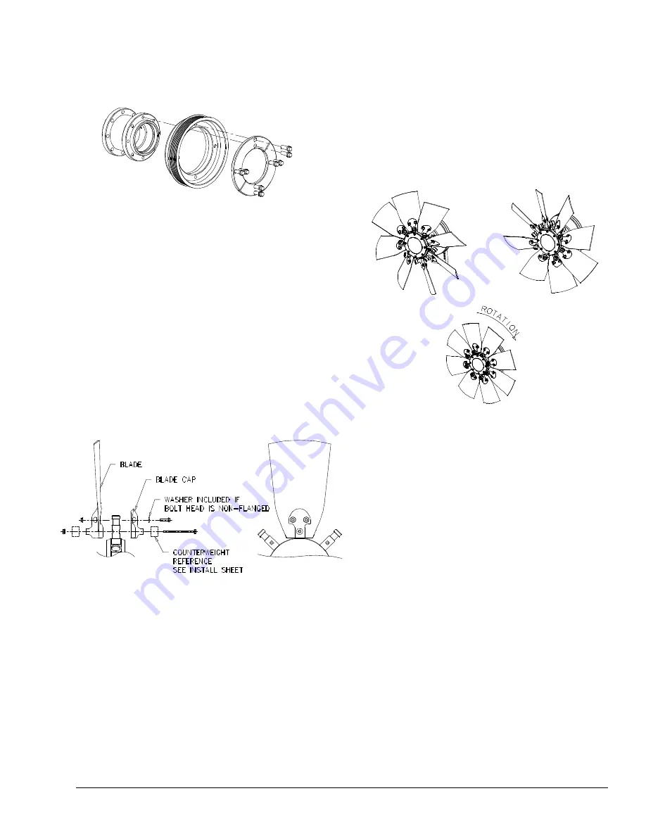
Figure 5
Figure 6, Push
Position
Figure 7, Pull
Position
Figure 8, Neutral
Position
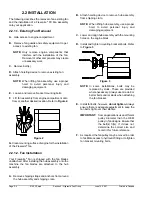
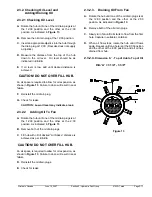
Some designs will require the removal of
capscrews and 2 half-moon rings or
equivalents (links); the pulley can then be slid
toward the hub to give easier access to the
hydraulic fittings, as shown in
Figure 4
.
Figure 4
G.
If the primary operation of the fan is to “pull” air
towards the engine, then the blades must be
mounted with the concave surface towards the
engine (assuming clockwise rotation of the fan). If
the primary operation of the fan is to “push” air
away from the engine, then the blades must be
mounted with the concave surface away from the
engine. The illustrations that follow show a fan that
primarily “pulls” air.
H.
The quantity and location of the counterweights
vary depending upon application. Please refer to
the install sheet supplied with your fan. Insert the
supplied 1/4" NC long hex bolt through the lower
hole in the blade cap, the blade shaft and the
blade. Tighten the assembly to the blade shaft
using the supplied 1/4" NC flanged lock nut.
I.
Insert the 1/4" NC short flange-head bolts through
the upper holes in the blade caps and blades.
Tighten the blade caps to the blades using the
supplied 1/4" NC flanged lock nuts. Regular hex-
head bolts with washers may be supplied in place
of flange-head bolts.
Note:
If any of the supplied flanged lock nuts are lost
or need to be replaced, they may be
substituted with grade 8 flanged nuts.
Loctite® 242 or equivalent must be applied
to the bolt if lock nuts are not used.
J.
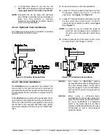
Rotate fan by hand in “PUSH”, “PULL” and
“NEUTRAL” modes (as shown in
Figure 6
,
Figure 7
&
Figure 8
respectively) to ensure that
the blade does not hit any obstructions such as
bolts, brackets, or braces. Secure remaining fan
blades. Carefully torque blade bolts with a
certified torque wrench to the following
specification:
1/4" - 20 NC to 9 ft./lbs.
WARNING - DO NOT OVER TORQUE
K.
Rotate fan blades once again by hand in
“NEUTRAL”, “PULL” and “PUSH” modes to
ensure that the blades do not hit any obstructions
such as bolts, brackets, or braces.
L.
Tighten fan belts and replace all fan guards and
safety equipment.
M.
Attach the "WARNING" label to the machine, on
a housing or guard, in a location near the fan
where it can be easily seen.
N.
Attach the "ATTENTION" label to the machine, in
the engine compartment, near the hub assembly
or another visible area.
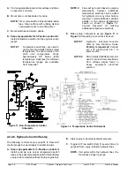
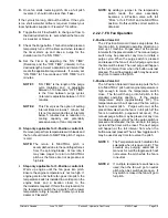
2.2.2. Hydraulic Control Installation Guide
The Flexxaire
®
FX Fan assembly requires a hydraulic
source and valving to operate.
Summary of Contents for FX 2000 Series
Page 2: ...Page 0 2 01523r7 wpd Hydraulic Manual June 14 2007 Printed in Canada...
Page 4: ...Page 0 4 01523r7 wpd Hydraulic Manual June 14 2007 Printed in Canada...
Page 6: ...Page 1 2 01523r7 wpd Section 1 General Information Overview June 14 2007 Printed in Canada...
Page 10: ...Page 2 2 01523r7 wpd Section 2 Hydraulic Fan Group June 14 2007 Printed in Canada...


