Page 2-8
01523r7.wpd
Section 2 - Hydraulic Fan Group
June 14, 2007
Printed in Canada
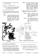
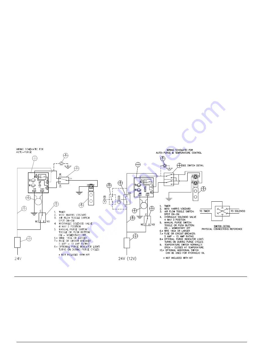
Figure 12, Temperature Control Schematic
A.
Find an appropriate location for switches and timer
on operator’s console.
B.
Mount timer onto backside of console.
NOTE:
Timer comes with 2 strips of double-sided
tape. Clean surface with rubbing alcohol
or equivalent prior to mounting timer.
C.
Mount switches and switch decals.
D. Step only applicable for 3-Position control kit.
Install temperature switch into the engine’s water
jacket.
NOTE 1:
Temperature switch(es) are used to
put the fan into full pitch at their rated
temperature. The fan remains in full
pitch until temperature drops
approximately 8
?
F below rated
temperature. Switch(es) for different
temperature ranges are available
from Flexxaire
®
.
NOTE 2:
Fans will go to pitch based on engine
temperature; however, additional
temperature switches can be added
for hydraulic oil or any other fluid as
required. Install additional switches
parallel to the engine temperature
switch as shown in
Figure 11
.
Contact Flexxaire
®
for ordering
additional temperature switches.
E.
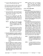
Make wiring connections as per
Figure 11
or
Figure 12
, depending on control kit be used.
NOTE 1:
Hydraulic solenoid connector
(Item 4) may contain a diode.
Polarity is important!
Connect
pin 2 to ground and pin 1 to
power source.
NOTE 2:
MOV (Harris V36ZA80) (Item 2) is
used to protect timer electronics
from voltage surges found in
heavy equipment electrical
systems.
Figure 11, Non-Temperature Control
Schematic
2.2.2.6. Hydraulic Control Set-Up
The following control set-up is specific to Flexxaire
®
control groups but would apply to similar set-ups.
A. Step only applicable for 3-Position control kit.
Install a jumper wire across temperature switch
leads, to by-pass temperature switch (this will allow
setup to be completed without having engine hot).
B.
Start engine to develop hydraulic pressure.
C.
Toggle Air Flow switch (Item 3) several times to
purge air from newly installed hydraulic lines.
NOTE:
If air exists within the hydraulic lines, the
fan will take longer to purge.
Summary of Contents for FX 2000 Series
Page 2: ...Page 0 2 01523r7 wpd Hydraulic Manual June 14 2007 Printed in Canada...
Page 4: ...Page 0 4 01523r7 wpd Hydraulic Manual June 14 2007 Printed in Canada...
Page 6: ...Page 1 2 01523r7 wpd Section 1 General Information Overview June 14 2007 Printed in Canada...
Page 10: ...Page 2 2 01523r7 wpd Section 2 Hydraulic Fan Group June 14 2007 Printed in Canada...


