background image

5

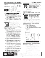
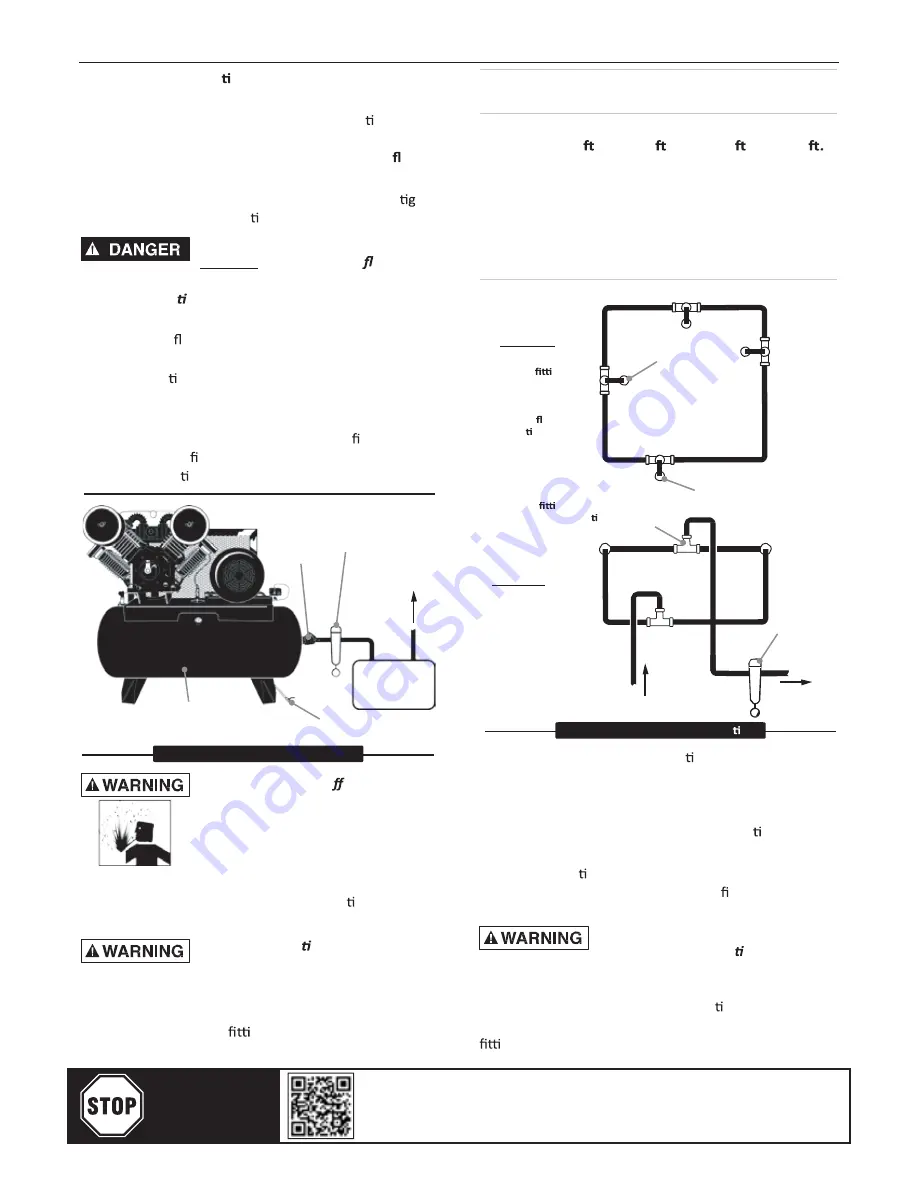
Piping / Tank  Installa on


1. Place tank feet on 1/4 in. thick rubber pads.

Thicker padding will increase vibra on and

the possibility of cracking the tank or other

unit damage. 

Do not place unit on dirt  oor

or uneven surface.

2. Fasten anchor bolts snugly but do not over ht- 

en so normal vibra on will not damage unit.

Compressor unit is top heavy  and 

  ,

d

il

o

s


o

d

e

tl

o

b


e

b

 t

s

u

m

at


surface to avoid falling and premature pump wear. 

Splash lubrica on will not operate properly if  unit 

is not  level.


3. Use a exible connector between compressor

(Pipe size shown in inches)


Length Of Piping System 

SCFM 

25  . 

50  . 

100  . 

250 

20 

3/4 

3/4 

3/4 

40 

3/4 

60 

3/4 

100 

1-1/4

  125 

1-1/4

1-1/4

1-1/2

1-1/2

PLAN VIEW


tank and piping system to minimize noise, 

vibra on, unit damage  and pump wear. 

4. Install appropriate ASME code safety  valves

and make sure piping system is equipped with

adequate condensate drains. See  gure  2.

Refer to  gure 3 for recommended closed loop

installa on.

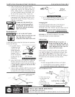
Closed loop  system


Install  tee 

ng 

in piping from  air 

supply to minimize 

pressure drop and 

to allow air ow in 

two direc ons.


Air Drop:


Air Drop 

(typ.)


From Compressor


Ball 

Valve


Coalescing Filter 

with Auto Drain


To Shop 

Piping


Install tee 

ng  with branch to top 

to minimize condensa

p

o

r

d


ri

a


n

n

o


ELEVATION


Water trap 

with drain


Air Tank


Air Dryer


From 

Compressor


To Air Tool


Water Drain Valve


Figure 2: Basic Piping Diagram 

Never install a shut-o  valve such  as 

a glove or gate valve, between the 

pump discharge and the air  tank 

unless a safety valve is installed in 

the line between valve and pump.


5. Make sure any tube, pipe or hose connected

to  the  unit  can  withstand  opera ng  tem- 

peratures and retain pressure.

Never use plas c (PVC) pipe for 

compressed air. Serious injury  or


death could  result.


6. Never use reducers in discharge piping. Keep

all piping and 

ngs the same size in the

piping system.

Figure 3: Closed Loop Installa on 

7. For permanent installa ons of compressed

air systems, determine total length of sys- 

tem and select correct pipe size. Make sure

underground lines are buried below frost line

and avoid areas where condensa on could

build up and  freeze.

8. Test en re piping system 

before 

underground

lines  are  buried.  Be  sure  to  nd  and  repair

all leaks before using compressor.

Never exceed  recommended pressure 

or  speed  while  opera ng compressor.


Electronic Auto Drain 

(if equipped)


One auto drain can be used for mul ple compres- 

sor  units.  Install  necessary  piping  with  appropriate 

ngs. 

Minimum Pipe Size For Compressed Air Lines

Operat ing, Service and Warranty Manual

Flexzilla® Pro Piston Air Compressors with Silencer™, Electric Operated

YOU MUST

REGISTER TO

ACTIVATE

WARRANTY

Scan or go to website hosted below:

www.eatoncompressor.com/warranty

Warranty only valid by following conditions expressed in the Warranty Statement section of this Air Compressor Manual.

Summary of Contents for FXS07V080V1

Page 1: ...anty Manual Published 2018 05 14 Revised 2022 11 08 responsible IMPORTANT MUST READ NEED TO CONFIRM WHETHER YOUR ELECTRICAL SYSTEM IS 1 PHASE OR 3 PHASE IF 3 PHASE MUST CONFIRM VOLTAGE FOR 3 PHASE COM...

Page 2: ...ase 39 175 10 HP 1750 208V 230V APP4V1043T 800 NPT 3 4 1020 1200 34 2 Contents Warranty Activation 2 Model Specification Charts 2 Description 2 Safety Information 3 Tag Definitions 3 Basic Guidelines...

Page 3: ...ons Death or serious injury can result from inhaling compressed air without using proper safety equipment See OSHA standards on safety equipment 2 DO NOT use air line an icer systems in air lines sup...

Page 4: ...t safety relief valves and drain valves from freezing NEVER operate compressor with temperatures below 15 5 2 1 e v o b a r o F F 2 Allow su cient space around compressor for maintenance access and ad...

Page 5: ...er From Compressor To Air Tool Water Drain Valve Figure 2 Basic Piping Diagram Never install a shut o valve such as a glove or gate valve between the pump discharge and the air tank unless a safety va...

Page 6: ...eaker NFB according to kW output of compressor 3 Ensure incoming service has adequate ampere ra ng 4 Ensure supply line has the same electrical char acteris cs voltage cycles and phase as the electric...

Page 7: ...d n a t s r e d n u d n a d a e r d n a g n i ons Keep all ammable combus ble poisonous and noxious materials away from opera ng area Make sure there are no oily rags trash leaves li er or other combu...

Page 8: ...un feature open ball valve found by following copper tubing across cylinder heads to tank See gure 9 Stop con nuous run feature by closing valve so com h c t i w s e r u s s e r p o t g n i d r o c c...

Page 9: ...12 1 bar DO NOT a empt mately 1 2 inch of de ec on 1 2 De ec on e r u s s e r p r e d n u s i e n i h c a m e l i h w e v l a v n e p o o t Tank 2 Adjust belt tension as needed by loosening the four...

Page 10: ...pressor 8 Increase ven la on around opera ng area Ensure compressor has adequate clear space from walls and other possible obstruc ons Ambien emperature should not exceed 11 F Check for proper oil lev...

Page 11: ...s rst Always maintain proper oil level in unit If the unit runs out of oil due to neglect the warranty will be void Use only Flexzilla approved oils in your compressor or your warranty is void Extende...

Page 12: ...dule Warranty shall be voided under the following condi ons Exposing electrical components to rain or water or installing the unit in a hos le environment such as acid vapors or any caus c or abrasive...

Reviews: