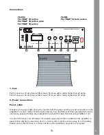
Ground Cable
The ground cable needs to carry the same current as the power cable. Again at least and 10
gauge cable should be used. The amplifier ground should be connected directly to the chassis of
the vehicle, to bare metal (not painted surface). The cable length should be kept to an absolute
minimum.It is not recommended that you connect the ground cable to the vehicles seatbelts.
Remote Turn On
A minimum of 18 gauge cable should be used for this connection. The cable should be run with
exactly the same care and attention as the power cable and taken back to the source and joined
to the remote cable provided on the head unit.
If the headunit does not have a remote turn on cable then a 12v supply should be used. This will
require a switch to be fitted inline to enable the amplifier to be turned on and off.
NOTE: Remember that if this switch is left on you will flatten the car battery.
3. Power/protection LED’s
When the amplifier is wired and installed correctly the green LED on the front of the amplifier will
illuminate to indicate the amplifier is operating correctly.
If the amplifier is incorrectly wired or an abnormal situation occurs such as speaker cables
shorting the red protection LED will illuminate.
4. Crossover frequency control
This will allow you to set the frequency at which the amplifiers low pass filter will take affect. This
is variable from 50 – 250 Hz. 50 Hz will produce only low frequencies (deep bass), 250 Hz will
produce low and higher, more punchy bass response.
5. Bass boost
This will allow you to boost the bass at a frequency of 45 Hz and is variable from 0 – 12dB
Please note – by bo12dB you are asking the amplifier to work 8 times harder.
6. Gain control
Used to match the input signal of the headunit to the amplifier. See the setup section for more
details. Please note – the gain control is not a volume control it is a level match.
7. Low level input
For connection to any source with a low level output. Connect this to the RCA outputs on your
head unit.
8. High level input
For connection to a source unit without low level outputs. Connect this to the front or rear
speaker wires ensuring that the polarity is correct.
6
Summary of Contents for TRAP 10A
Page 1: ...trap active enclosures www fliaudio com Models TRAP 10A 10AP 12A 12TA ...
Page 9: ...notes ...
Page 10: ...notes ...


