background image

4

Active enclosure Installation

Your FLI UNDERGROUND enclosure is designed with a swift installation routine in 

mind. Please mount the enclosure in a dry location on a solid surface. NEVER mount the 

enclosure upside down, this will cause the ampli

fi

 er to overheat and will eventually damage 

the ampli

fi

 er. Before 

fi

 xing the enclosure in place please ensure that there is suf

fi

 cient air 

fl

 ow around the ampli

fi

 er heatsink, at least two inches will be suf

fi

 cient.

Power Cable

• At least a 10 gauge cable should be used for both the power and the ground connections to the 

ampli

fi

 er.

• The power cable should be taken directly from the battery. Rubber grommets should be used 

when passing through any bulkheads to prevent the cable from becoming chaffed or cut.

• It is vital that a fuse / circuit breaker (of at least equal value to the one 

fi

 tted on the ampli

fi

 er) is placed 

in line with the power cable and is no further than eighteen inches away from the battery.

• Please ensure that the fuse is not 

fi

 tted until the entire installation procedure is complete.

• The two tables below are to help you decide on what cable is correct for you. The 

fi

 rst enables you to 

select the size of cable depending on the length required. The second will help you convert the cable size 

from American Wire Gauge to Metric if you need to.

Length of Run

Current demand

0 – 4 Ft

4 – 7 Ft

7 – 10 Ft

10 – 13 Ft

13 – 16 Ft

16 – 19 Ft

19 – 22 Ft

22 – 28 Ft

0–20 amps

14

12

12

10

10

8

8

8

20–35 amps

12

10

8

8

6

6

6

4

35–50 amps

10

8

8

6

4

4

4

4

50–65 amps

8

8

6

4

4

4

4

2

65–85 amps

6

6

4

4

2

2

2

0

85–105 amps

6

6

4

2

2

2

2

0

105–125 amps

4

4

4

2

0

0

0

0

125–150 amps

2

2

2

0

0

0

0

0

AWG

A

A

to Metric Conversion Chart

cross sectional area

AWG

A

A

Number

Inch

mm

mm2

0

0.325

8.25

53.5

1

0.289

7.35

42.4

2

0.258

6.54

33.6

3

0.229

5.83

26.7

4

0.204

5.19

21.1

5

0.182

4.62

16.8

6

0.162

4.11

13.3

7

0.144

3.66

10.5

8

0.128

3.26

8.36

9

0.114

2.91

6.63

10

0.102

2.59

5.26

1 M e t r e – 3 . 2 8 F e e t

Summary of Contents for UNDERGROUND FU10A

Page 1: ...UNDERGROUND INSTRUCTION INSTALLATION MANUAL MODEL FU10A FU12A FU12TA active enclosure...

Page 2: ...thoroughly Use caution when working near the fuel hydraulic lines and electrical wiring Observe the correct polarity when wiring improper phasing may cause a loss of bass response Ensure that no movi...

Page 3: ...put of it will increase as the suspension loosens up A new subwoofer is like a new car engine it needs a few thousand miles before you can drive it to its full potential driving it into the red line f...

Page 4: ...ith the power cable and is no further than eighteen inches away from the battery Please ensure that the fuse is not fitted until the entire installation procedure is complete The two tables below are...

Page 5: ...attention as the power cable and taken back to the source headunit and joined to the remote cable provided If the source headunit does not have a remote turn on cable then a 12v supply should be used...

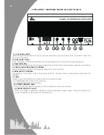
Page 6: ...TROL High pass frequency control The frequency ranges from 50hz to 250 Hz E BASS BOOST CONTROL To provide up to an extra 6 dB of bass boost at 45 Hz Use this boost to increase bass output from the amp...

Page 7: ...an be heard in any of the speakers or until the volume reaches an uncomfortable listening level when this is reached turn down the gain control slightly The gain control is now set The setting of the...

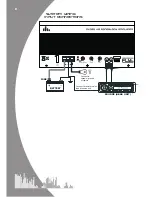
Page 8: ...8 System Wiring Input connections BATTERY FUSE Connect to chassis ground of vehicle Connect to remote turn on lead of source unit SOURCE HEAD UNIT...

Page 9: ...utomatically when the units temperature goes above 80 degrees If the amplifier feels very hot then this may be the reason for the amplifier not starting Check that there is good airflow around the amp...

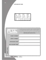
Page 10: ...e for your future reference For more information and to register your warranty online visit www fliaudio com warranty Model Driver Amplifier RMS power Peak power Impedance Height Depth Width FU12TA FU...

Page 11: ...graphics logos icons images data the selection and arrangement thereof are the property of FLI Audio herein referred to as FLI us or we and its affiliate or their content and technology providers and...

Page 12: ...watts 270 watts speakers FU 4 FU 5 FU 6 FU 69 FU 5c FU 6c FU 10 FU 12 FU 15 FU 360 FU 720 FU 1000 1 FU 1000 5 FU 10P FU 10A FU 12P FU 12A FU 12TP FU 12TA up to up to 1200 watts 1200 watts up to up to...

Reviews: