2
Revision G, November 2009
Installation Instructions
All cabin entertainment equipment, such as the DAPS350, should be installed on
a non-essential bus and have a dedicated circuit breaker. It is a requirement that
a switch be installed so that the pilot can de-energize the system should it
become necessary.
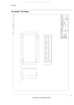
There are four mounting slots located on the sides of the DAPS350 on the sides
for horizontal mounting and two slots on the end for vertical mounting. It is
sufficient to mount the unit by only two attach points. This unit can be mounted
in any orientation. Care should be given to make sure the DB Connectors are
firmly seated in the VGA inputs and outputs and that the aircraft wire bundle will
not shift and pull the plugs away from the DAPS350.
The unit will come on automatically upon applying power. During check out you
can look to see that the power LED is illuminated once power has been applied.
Install VGA cables in the numerical order as indicated on the DAPS350 labeling.
Note: Maximum length from the source to the DAPS350 is 25’, and maximum
length from the DAPS350 to the displays is 250’.
Power
This is a
28VDC
device that requires 2.5 Amps of power to operate.
Video Wiring Suggestions
All shields should be grounded to the connector at the source, and floating at the
display.
Avoid routing video wiring parallel to:
•
AC wiring
•
Strobe wiring
•
DC motor supply cables
•
Inverter cabling
•
Or any other potential noise source.
All manuals and user guides at all-guides.com


