der and trim tab has been modified with the ad-
dition of an 8” strap to the top trailing edge
of the rudder trim tab, and a 6” strap to the rud-
der training edge. With this modification to re-
duce yaw oscillations (Dutch roll), use of the
yaw damper becomes optional.
Rudder Pedals
The rudder pedals are used to operate brakes,
nose wheel steering, and rudder.
Rudder pedal adjustment actuators allow in-
dependent adjustment of rudder pedal position.
The pedals can be adjusted approximately 8
inches in the forward and aft range. The rud-
der adjustment actuators receive electrical
power through the L RUD ADJUST and R
RUD ADJUST circuit breakers located in the
FLIGHT group on the respective left and right
side circuit breaker panels.
Rudder Trim
A rudder trim tab is connected to the trailing
edge of the rudder with a continuous type
hinge (Figure 15-11). The trim tab is posi-
tioned with dual pushrods connected to a ro-
tary-type electrical actuator installed in the
rudder leading edge.
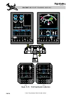
Rudder trim is controlled through the spring
loaded rudder trim switch located on the cen-
ter pedestal (Figure 15-12). The switch is a hor-
izontally split knob, providing an upper and
lower half. Both halves must be rotated si-
multaneously to initiate rudder trim. This is
a safety feature to reduce the possibility of in-
advertent trim actuation.
Electrical power for rudder trim is provided
by the R Essential Bus through the TRIM-
RUD circuit breaker located in the FLIGHT
group on the copilot's circuit breaker panel.
Uncommanded rudder trim can be stopped by
depressing and holding either Control Wheel
Master Switch (MSW).
There are no CAS or CWP indications for the
rudder trim system. A normal approach and
landing can be made with only light control
forces to overcome full rudder trim.
Yaw Servo
The yaw servo is used by the yaw damper and
the rudder boost.
The yaw servo is a two direction torque motor;
it incorporates an electrical clutch that en-
gages only when the yaw damper is engaged
or when the rudder boost is applying rudder
pressure. When the clutch is engaged, the servo
is connected to a capstan that is connected to
the aft rudder sector with cables (Figure 15-10)
If there is a conflict between the yaw damper
and the rudder boost in use of the yaw servo,
the rudder boost will take priority. The Airplane
Flight Manual prohibits having the yaw damper
and rudder boost on at the same time on un-
modified aircraft. On aircraft 45-170 and sub-
sequent and earlier aircraft modified by SB
45-22-4, the yaw damper and rudder boost can
be on at the same time.
If a system malfunction causes the yaw servo
to produce an undesired input, either Control
Wheel Master Switch (MSW) can be depressed
a n d h e l d t o d i s e n g a g e t h e s e r vo c l u t c h .
Depressing the MSW will disconnect the yaw
damper and the rudder boost will be disabled
while the MSW is held depressed. If the mal-
function is isolated to the rudder boost, the
RU D D E R B O O S T s w i t c h o n t h e c e n t e r
pedestal can be selected to OFF (Figure 15-12).
T h e y aw s e r vo r e c e ive s e l e c t r i c a l p ow e r
through the AFCS SERVOS circuit breaker
located in the FLIGHT group on the pilot's cir-
cuit breaker panel.
Rudder Boost
The rudder boost system is installed to assist
the crew when heavy rudder pedal force is re-
quired to maintain directional control, such as
with engine failure during takeoff.
Rudder boost provides yaw servo torque pro-
portional to rudder pedal force, when the pi-
lot's, copilot's or sum of the pilot's and copilot's
15-11
FOR TRAINING PURPOSES ONLY
L E A R J E T 4 5 P I L O T T R A I N I N G M A N U A L
FlightSafety
international


