FP (Flight plan) –
Selecting this mode
places the radar in the flight plan mode per-
mitting the singular display of navigation data
on the PFDs/MFD. There is no radar data pre-
sent. In FP, the radar is put into the STANDBY
mode and the “FLT PLN” legend is displayed.
If target alert (TGT) is selected, the radar will
continue to transmit. The normal limit for
range selection on the radar (PFD/MFD dis-
plays) is 300 NM, but with FP selected, ranges
up to 1,000 NM can be selected.
TST (Test) –
When this mode is selected the
weather depiction will be a special colored
test pattern to allow verification of system
operation (Figure 16-52).
Additional Controls
Range –
Two pushbutton switches on the
radar control panel are used to select the op-
erating range of the radar (Figure 16-51). One
switch has an up-arrow to increase the range,
and the other has a down-arrow to decrease the
range. The range selections when WX is dis-
played on the PFDs or MFD are 5, 10, 25, 50,
100, 200, or 300 NM. One-half of the selected
range value is annunciated next to the mid-
range arc on the DUs. With FP selected on
the radar mode switch, a 500 and 1,000 NM
range can be selected.
Gain –
The rotary control knob varies the re-
ceiver sensitivity (gain). The system is in the
variable gain mode with the control knob
pulled out and preset (fixed) gain with it
pushed in. The “VAR” legend is displayed
when the system is in the variable gain mode.
Preset gain is the recommended setting for
WX mode. Gain, fixed or variable does not an-
nunciate on the radar displays.
Engaging RCT or TGT overrides the variable
gain selection and puts the system into the
fixed gain mode.
Tilt –
A rotary control knob on the right side
of the radar control panel is used to select tilt
angle of the antenna. Clockwise rotation tilts
the beam upward from 0° to + 15°, and counter-
clockwise rotation tilts the beam downward
from 0 to - 15°. Autotilt is enabled by pulling
out on the tilt knob. Autotilt automatically ad-
justs tilt during altitude and range changes.
Manual tilt commands through the tilt knob
may be made with AUTO selected. Tilt is in-
dicated just below the weather mode annun-
ciator at the left end of the mid-range arc on
the PFDs (Figure 16-51). On the MFD, tilt is
indicated just below the weather mode an-
nunciation on the left side of the display.
L E A R J E T 4 5
P I L O T T R A I N I N G M A N U A L
16-95
FOR TRAINING PURPOSES ONLY
FlightSafety
international
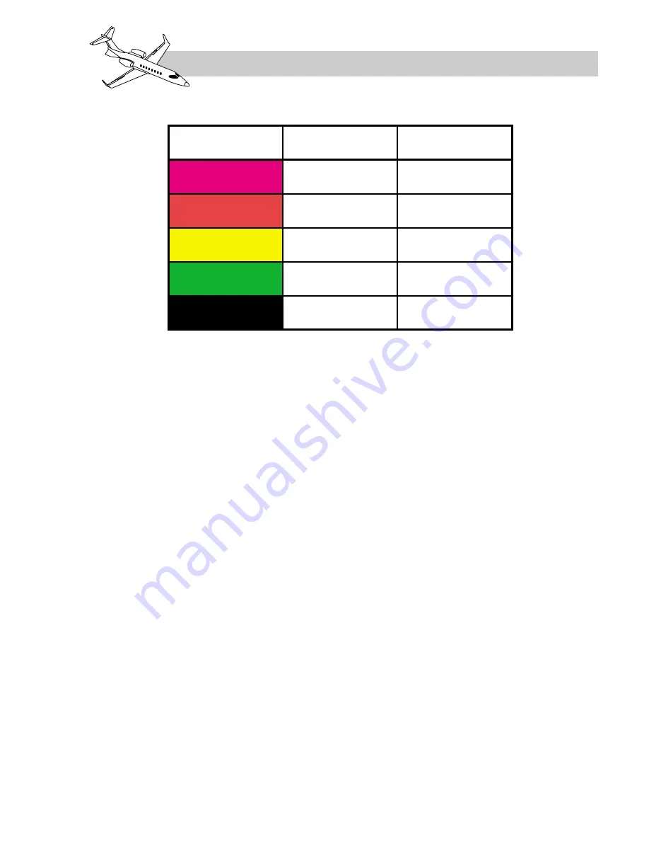
DISPLAY
LEVEL
RAINFALL RATE
(IN/HR)
STORM
CATEGORY
4
MAGENTA
3
RED
2
YELLOW
1
GREEN
0
BLACK
GREATER THAN
2.1
0.5 – 2.1
0.17 – 0.5
0.04 – 0.17
LESS THAN 0.04
EXTREME/INTENSE
STRONG
MODERATE
WEAK
N/A
Table 16-7. WX RADAR STORM INTENSITY LEVELS


