The transponder selection options for a TCAS
I equipped airplane will be STANDBY, ATC
ON, ATC ALT and TA. Selections available
with TCAS II include the same as TCAS I
plus TA/RA. The selected TCAS mode will be
annunciated in the top left corner of the TCAS
display. See Figures 16-54, 16-55 and 16-56
for TCAS annunciations.
Relative/Absolute
Intruder altitude information is normally de-
picted as relative, and is expressed as a plus
or minus number in hundreds of feet. The crew
can switch the altitude display to absolute for
short periods if desired. Absolute can be se-
lected on the ATC/TCAS CONTROL PAGE
(Figure 16-14). When selected, the absolute
altitude is displayed in place of the relative al-
titude data tag and will consist of three digits
indicating hundreds of feet. Whenever abso-
lute altitude is being displayed, a “FL” (flight
level) annunciator appears in the upper left cor-
ner of the TCAS display. When selected, ab-
solute altitude is only displayed for 20 seconds,
then automatically returns to a relative display.
Auto/Manual TCAS Display
The TCAS traffic map can be displayed on
the MFD automatically or manually. Use the
TA DISPLAY function on the ATC/TCAS
CONTROL PAGE of the RMU (Figure 16-14)
t o s e l e c t b e t w e e n AU TO a n d M A N UA L
modes. When AUTO mode is selected, the
TCAS window on the MFD will automatically
pop up anytime a TA or RA is detected. The
TCAS display cannot be removed from the
MFD until the conflict has passed and no RAs,
TAs, or proximity traffic are displayed. When
MANUAL mode is selected, the TCAS bezel
button on the MFD is alternately depressed to
display and remove the TCAS display.
Range
TCAS range is selected on the RMU main
radio tuning page. The TCAS window pro-
vides for annunciation and control of range and
altitude band selection. Placing the cursor
over the RANGE field allows the operator to
adjust the TCAS range display on the MFD to
either 6, 12, 20 or 40 NM using the RMU tun-
ing knob, or depressing the adjacent line se-
lect key multiple times. On aircraft 45-170
and subsequent and earlier aircraft modified
by SB 45-22-4, ranges of 80 and 120 NM may
be selected.
Whenever TCAS range is selected to less than
20 NM, a ring of twelve small circles (or dots)
are placed in a radius of two nautical miles
around the airplane symbol. A full range arc
is displayed at the top limit of the display
(Figure 16-55). The two mile range ring is
displayed proportional to the current TCAS
range selection. The range selected is annun-
ciated at the right end of the full range arc.
When the range is set to 20 or 40 NM, a half-
range arc replaces the 2 NM ring. The range
is still annunciated at the full range arc (Figure
16-56).
L E A R J E T 4 5
P I L O T T R A I N I N G M A N U A L
16-102
FOR TRAINING PURPOSES ONLY
FlightSafety
international
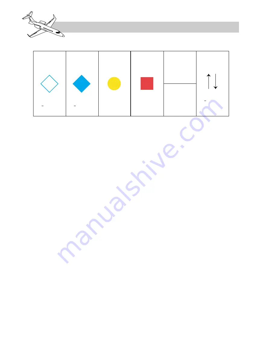
+ 20
Non-Threat
OTHER
TRAFFIC (OT)
PROXIMITY
ADVISORY (PA)
TRAFFIC
ADVISORY (TA)
RESOLUTION
ADVISORY (RA)
Non-Threat
Potential
Hazard
Collision
Threat
> + 500 fpm
RELATIVE
ALTITUDE TAG
ABSOLUTE
ALTITUDE TAG
060
(6,000 feet)
Filled
Red Square
Filled
Amber Circle
Filled
Cyan Diamond
< + 1,200 feet
and
< 6 NM
Open
Cyan Diamond
> + 1,200 feet
or
> 6 NM
TREND
ARROWS
Table 16-9. TCAS DISPLAY SYMBOLS


