OXYGEN SYSTEM
INDICATIONS
EICAS Indications
The oxygen cylinder transducer, located on the
shutoff valve and regulator, transmits both
oxygen cylinder temperature and bottle pres-
sure to data acquisition unit number 1 (DAU
1). The DAU then interfaces through the IC-
600s and the symbol generators to display
quantity values in liters on the EICAS/MFD.
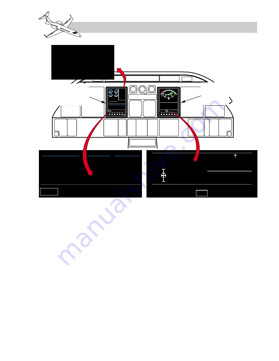
As illustrated in Figure 17-5, those indica-
tions can be displayed in a variety of locations.
On the EICAS display, with the SUMRY dis-
play option selected, quantity in liters is re-
ported at the bottom of the center column
under the HYD/ECS heading. Selecting the
ECS system schematic on the EICAS/MFD
provides oxygen quantity in a different format.
Oxygen duration is determined by entering a
duration chart in the
Airplane Flight Manual
or oxygen duration chart and tables in the
S u p p l e m e n t s e c t i o n o f t h e F l i g h t C r ew
Checklist with oxygen quantity expressed in
liters.
System Malfunction Displays
On the EICAS and MFD displays, as long as
the oxygen system operates normally, the
cylinder quantity reports are displayed in white
digits. Since the oxygen cylinder is located in
an unpressurized area of the airplane, the nor-
mal operating pressure ranges are affected by
temperature changes.
17-5
FOR TRAINING PURPOSES ONLY
L E A R J E T 4 5
P I L O T T R A I N I N G M A N U A L
FlightSafety
international
MULTI-
FUNCTIONAL
DISPLAY
(MFD)
ENGINE
INSTRUMENT
CREW ALERTING
SYSTEM (EICAS)
OXYGEN OFF
OXYGEN QTY LOW
OXY PRESS HI
PAX OXY FAIL
PAX OXY DEPLOY
ELECT
VOLTS
EMER-V
AMPS
TEMP
°
C
28.5 28.0
28.0
50
65
30
50
HYD/ECS
MAIN
B-ACUM
CAB ALT
OXY QTY
3000
3000
1300
FLT
SPLR
PIT
AIL
RUD
0
0
R 0
L 0
669
SUMRY ELEC HYD ECS FLT FUEL CAS
SUMRY ELEC HYD ECS FLT FUEL
RTN
CAB TEMP
78
°
F
TEMP CONT
CAB CKPT
H
C
OXY QTY
669
LTR
CABIN RATE
100
DELTA P
9.4
CABIN ALT
1300
MANUAL RATE
0
LDG ALT
2600
Figure 17-5. Oxygen System Indications


