Installation
Mounting the Control Panel
requires four holes in the instrument panel and can easily be secured in place
by the Volume Control mounting nut and a 4-40 screw. Refer to the DRILL DRAWING (Fig. 1) for correct
holes sizes and locations. In addition to the Fig. 1, a separate drilling template is enclosed.
Control Panel Label,
After the holes are drilled and the control panel is checked for proper mounting, the
Control Panel Label can be applied. Make sure the surface is clean form oil or drill chips. Remove the back
protective cover from the label and apply it to the instrument carefully aliening the holes. Insert the control
panel and install the Volume control nut.
Cable Connections
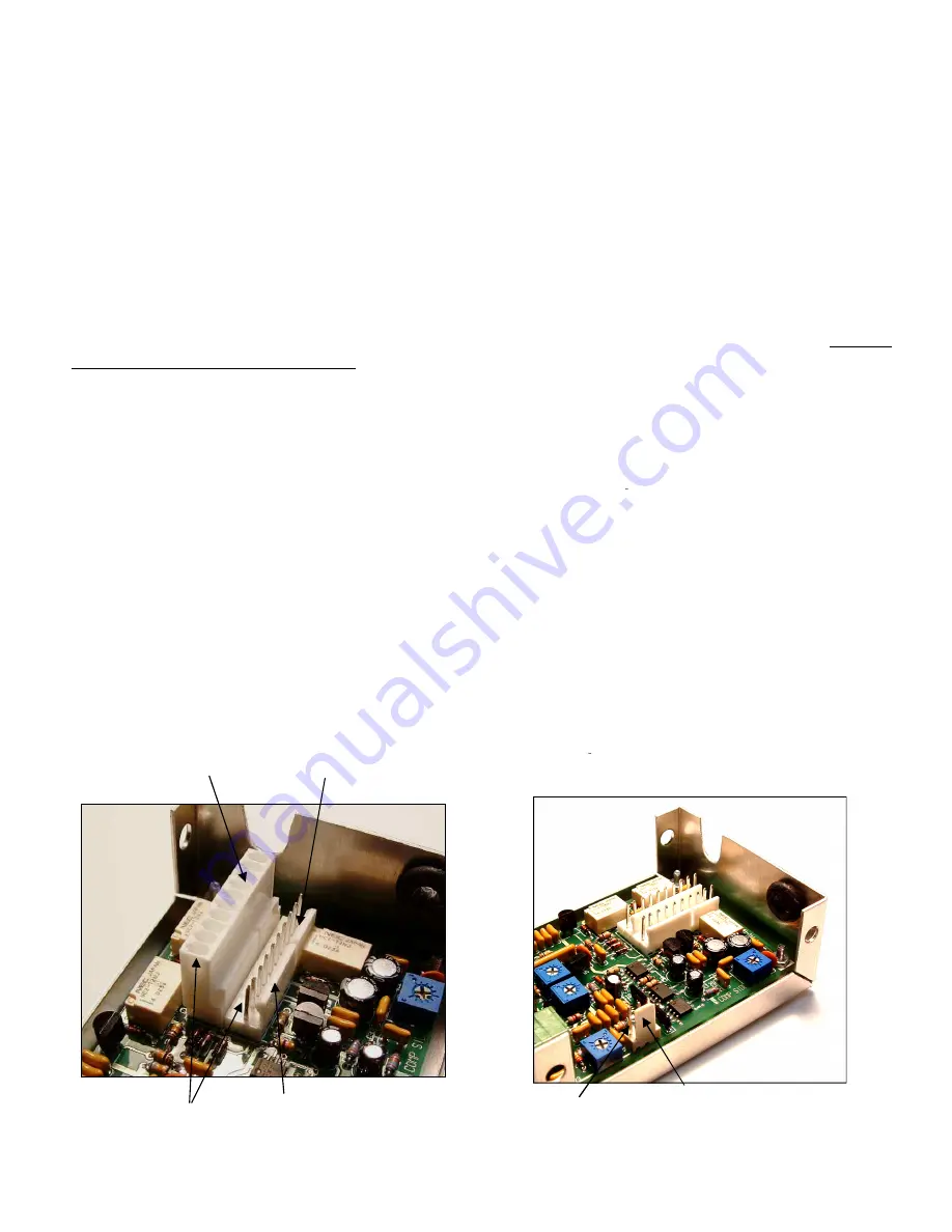
, The main cable is connected to the intercom through two ten pin connectors that pro-
vide the Power, Audio Inputs and Headphone connections for the Pilot, Co-pilot and Passengers.
Refer to
Page 8 for the connector connections.
The cable connector is a
Molex KK-100 Series
housing and crimp terminals. The terminals can be crimped
onto wire size ranging from 22 to 26 gage. 24 gage wire are recommended for the intercom installation.
Recommended tools for installing the terminals are, Molex Crimp Tool part # 11-01-0185 Hand Crimping
Tool.. Refer to the photo, on page 6 of the two 10 pin connectors for the locations of pin 1 through 10. Note
that there are locking and polarity tabs on the plug housing and socket housing. Refer to page 8 for the pin
connections.
Located along the side of the circuit board is J-3, a three terminal connector for the Cellular phone cable.
Refer to page 8 for the terminal connections.
Power (12-28 VDC) and Ground wires should be 22 Gage wire with a 1 amp fuse or circuit braker in line
with the Plus Voltage line.
Microphone cables as well as headphone cables should be a shielded cable . All ground or shield connections
should be terminated at one point at the connector.
3
Pin 1 Cell Phone Connector
Pin 1 Locking Tab.
Connectors J-1 J-2
Summary of Contents for ITC-404SP
Page 9: ...NOTES 9 ...


