


What the passive headphones do not do, is reduce or eliminate is the noise picked up by the headsets micro-
phone and heard when the intercoms audio path is open. This where the ENRI function comes into action,
eliminating or reducing the background noise heard by the headsets microphone.
NOTE: for best results, it is necessary to speak close to the headsets microphone.
ANR Headsets
ANR Headsets provide additional noise reduction at the headset’s ear cups but some back-
ground audio from the headsets microphone can still be heard. ANR headsets used in conjunction with the
ITC-404SP ENRI intercom will have an added benefit of no microphone noise. ANR headsets are not re-
quired for the Electronic Noise Reduction circuit to operate.
Push-to-Talk
The ITC-404SP features Pilot and Co-Pilot PTT function allowing either the pilot or co-pilot to key
and talk on the communication radio. When ever the pilots PTT is pushed, only the pilot will be able to talk
but when the co-pilot PTT is keyed, the audio path is switch from the pilots microphone to the co-pilots mi-
crophone. The pilot can still talk through the intercom but not to the radio.
Auxiliary Stereo Audio & Muting Function
When a device such as a CD player is connect to the intercom and stereo headphones are used, pilot
and passengers can enjoy music while on long trips.
The Auxiliary Audio will mute when one of two things take place.
1.
When ever there is audio present from the communication radio.
2. During Intercom communications.
The muting action from either source will effect all the headsets and auxiliary audio will remain muted for
several seconds after the intercom audio or radios audio stops.
Intercom Internal Adjustment
•
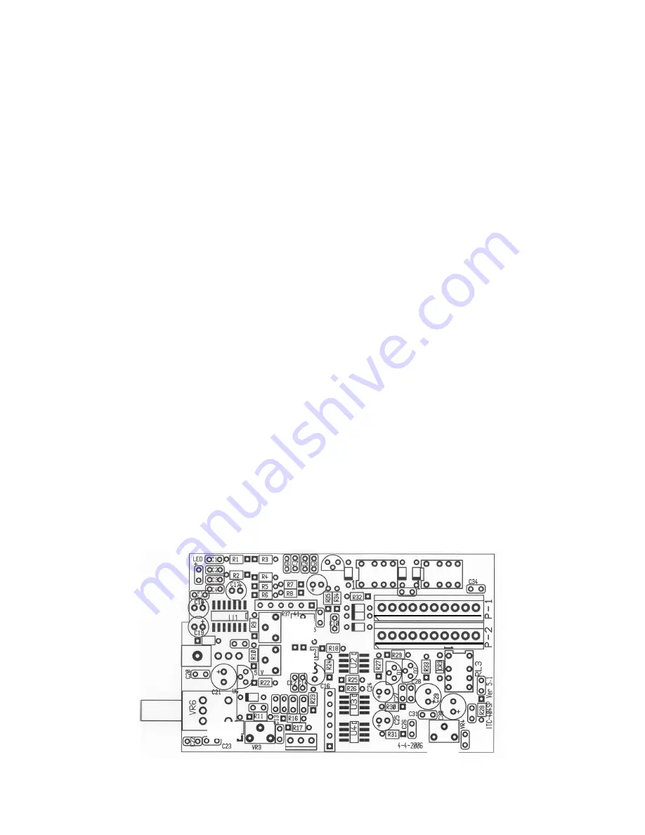
There are four potentiometers located on the intercom circuit board VR-1 Microphone Gain, VR-2,
Noise Reduction, VR-3, Cell Phone Mic Level and VR-4, Radio Audio Balance. All the pots are set at
the factory for normal operation but depending on the type of headphone and ambiament background
noise during flight, some minor adjustment may be required. To make any changes, remove the top
cover and refer to Fig 8 for the locations of VR-1, VR-2, VR-3 and VR-4.
5
P-3, Pins 1 2 3
VR-1
VR-2
VR-3
VR-4
*LisghtSpeed mic gain adjustment is located on the
back side of the microphone.
Summary of Contents for ITC-404SP
Page 9: ...NOTES 9 ...


