background image

4-40 x 3/8 screw

Volume Control Nut

Instructions for FAA Form 337 


The ITC-404SP can usually receive an airworthiness approval by submitting the FAA form 337, 

Major Repair and Alteration 

(Airframe, Power plant, Propeller or Appliance) .  For the ITC-404SP, the following text can be used as a guide. 


1.  Installed FlightTech ITC-404SP Panel Mount Intercom, as per the manufactures instructions provided by the manufac-

turer, DesignTech Systems. 

2.  Installed intercom unit (location in instrument panel) in plane sight of the pilot and connected to the avionics buss 

through a 1 Amp fuse.  Jacks were installed on each side (location).  Push-To-Talk buttons installed (locations). 

3.  This unit has a fail-safe feature built-in, in the event of a power failure to the intercom, the pilots headset can be con-

nected directly to the radio headphone input and microphone. 

4.  All work was done in accordance with manufacturer’s instructions, FAR43, AC43.13-1B Chapter 11 (Electrical Systems), Sec-

tion 5 (electrical wire rating), Section 6 (aircraft electrical wire selection), Section 7 (table of acceptable wires), Section 8 

(wiring installation requirements), Section 9 (environment protection and inspection), Section 11 (clamping), Section 12 

(wire insulation and lacing string tie), Section 13 (splicing), Section 15 (grounding and bonding), Section 17 (connectors), 

AC43.13-2A Chapter 2 (Radio Installations). 

5  Weight and Balance/Equipment list was amended. 

6  Instructions for continued airworthiness: Annual visual and operational inspection as per AC43.13-1B, Chapter 12, Section 1, 

-1 (Avionics equipment maintenance), 12-9a (inspection of avionics systems). 

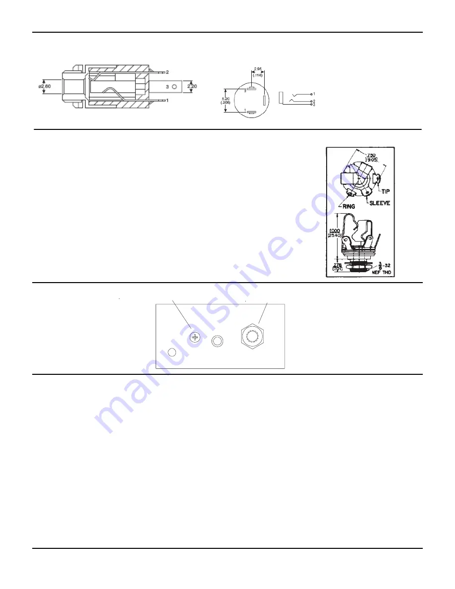
2.5 mm Cellular Phone jack. 

Pin 1, Mic to J3-1 
Pin 2, Audio to J3-2 
Pin 3, shield to J3-3 

Microphone and Stereo Headphone Jack 

Summary of Contents for ITC-404SP

Page 1: ...1 FlightTech Intercom ITC 404SP Four Place Stereo Panel Mount Intercom with Enhanced Noise Reduction Technology FlightTech Intercoms ...

Page 2: ...mmunications radio and be able to speak Auxiliary Audio Stereo Input A Stereo Auxiliary input is provided allowing a tape or CD player to be connected to the ITC 404SP The audio output is Stereo and requires Stereo headphones for proper operation Auxiliary Audio Muting The Auxiliary audio will mute when audio form the Communication radio or Intercom audio occurs Cellular Phone Interface The Cell P...

Page 3: ...r to Page 8 for the connector connections The cable connector is a Molex KK 100 Series housing and crimp terminals The terminals can be crimped onto wire size ranging from 22 to 26 gage 24 gage wire are recommended for the intercom installation Recommended tools for installing the terminals are Molex Crimp Tool part 11 01 0185 Hand Crimping Tool Refer to the photo on page 6 of the two 10 pin conne...

Page 4: ... s PTT Operation of the ITC 404SP The ITC 404SP is one of the simplest intercoms available to operate plug in the headphones turn on the power and start talking It s that easy With the ITC 404SP Enhanced Noise Reduction circuit there are no squelch controls or functions to con tend with Since there are no squelch function either manual or automatic it is not necessary to kick start the audio with ...

Page 5: ...ts microphone to the co pilots mi crophone The pilot can still talk through the intercom but not to the radio Auxiliary Stereo Audio Muting Function When a device such as a CD player is connect to the intercom and stereo headphones are used pilot and passengers can enjoy music while on long trips The Auxiliary Audio will mute when one of two things take place 1 When ever there is audio present fro...

Page 6: ...ng the microphone level control for the lower setting During normal cruise power setting there should be no outside noise com ing through the intercom Communication Radio Line Balance When toggling the Pilot ISO switch a difference in the radio audio level may be heard To correct this level difference a level balance pot VR 4 can be adjusted to set the audio level Locate VR 4 and while listening t...

Page 7: ...ots headset can be con nected directly to the radio headphone input and microphone 4 All work was done in accordance with manufacturer s instructions FAR43 AC43 13 1B Chapter 11 Electrical Systems Sec tion 5 electrical wire rating Section 6 aircraft electrical wire selection Section 7 table of acceptable wires Section 8 wiring installation requirements Section 9 environment protection and inspecti...

Page 8: ...the ITC 2003 stereo intercom install a 33 ohm 1 4 watt resistor to the TIP and RING of each headphone jack HEADPHONE JACK 33 OHM Resistor White White White White White White White Wh Bl White Blue White White Blue White Blue Cable wire colors are for FlightTech supplied cables Passanger 1 Ch 1 Passanger 1 Ch 2 White Blue Microphone Jack from radio cable Headphone Jack from radio cable G ND G ND Gr...

Page 9: ...NOTES 9 ...

Page 10: ...6 00 within USA and it will be repaired or replaced within two weeks Warranty does not cover transportation cost or product misuse accidental dam age owner tampering or reworking Except as provided herein either FlightTech Intercoms or DesignTech Systems makes no warranties expressed or im plied including warranties or merchantability and fitness for a particular purpose NOTE Some states do not pe...

Reviews: