Kabelanschlusskasten Typ KP Technisches Handbuch Rev. 1.01 September 2016
Junction Box Type KP Technical Manual
Seite / Page 7/8
I
NTRODUCTION AND TECHNICAL
D
ATA
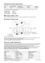
The Polyester junction box is designed for the parallel connection of up to 4 load cells.
Type
No. of load cells
Housing size
Inputs
Output
KP-4
up to 4
75 x 230 x 50 mm
4x M12
1x M16
The junction box type KP can be connected to the instrumentation with a shielded 6-wire signal cable.
The corner correction is done with resistors.
Housing material:
Polyester
Protection class:
IP66
Cable connection:
By soldering
Corner correction:
By resistors
M
ECHANICAL
I
NSTALLATION
Look for a mounting location which is more or less dry and protected from environmental stress.
E
LECTRICAL
C
ONNECTIONS
2
1
2
1
2
1
2
1
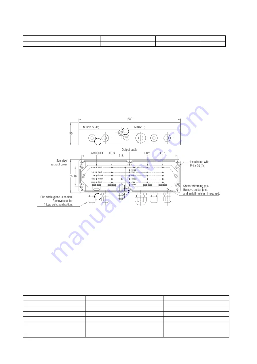
Figure 1: Dimensions in [mm]
The earth screw (see (2) in fig.1) has to be connected to protective earth or you must establish an electrical
connection to the weigh modules for potential equalisation.
The connection sequence of the load cells should correspond to the corners of the scale, i.e
Corner 1 = Load cell 1, Corner 2 = Load cell 2, etc.
L
OAD
C
ELL
C
ABLE
C
ONNECTION
First the cable gland (see (1) in fig.1) must be loosened. Then you have to feed the load cell cable through the
cable gland unless the shrink tube is fully disappeared in the box. The wires have to run below the printed
circuit board and will be pulled back to the top at the upper end of the printed circuit board.
Then feed the tin-plated wires through the hole at the solder point. Use a suitable soldering iron for electronic
works (at least 30 Watt ). Proper solder joints always look bright and shiny.
Never use soldering solution and soldering grease! This will destroy the printed circuit board!
Always use suitable electronic solder, e.g. S-Sn60Pb40 DIN EN 29453.
The wires have to be connected as follows:
Cable coulour
Description
Solder joint designation
yellow
= Cable shield
Shield / Schirm
red
= Signal
– (Output –)
red / rot
white
= ()
white /weiss
black
= Excitation
– (Input –)
black / schwarz
(if applicable, brown)*
= Sense
–
black / schwarz
green
= Exci (Input +)
green / grün
(if applicable, blue)*
= Sense +
green / grün
* if load cell is equiped with 6-wire conductor cable


