Installation
7
7.6
Back cover
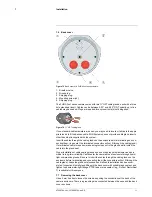
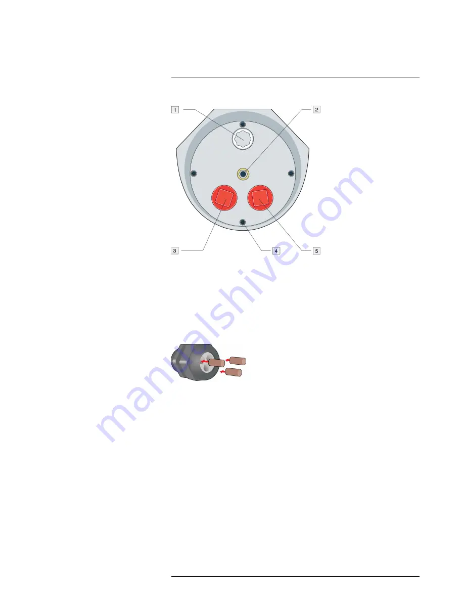
Figure 7.3
Back cover of a FLIR A3xx f series camera.
1. Breather valve.
2. Ground lug.
3. Shipping plug.
4. Mounting screw (×4).
5. Shipping plug.
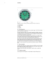
The FLIR A3xx f series camera comes with two ¾″ NPT cable glands, each with a three-
hole gland seal insert. Cables can be between 0.23″ and 0.29″ OD. Typically, up to five
cables may be needed. Plugs are required for any insert hole(s) not being used.
Figure 7.4
¾″ NPT cable gland.
If non-standard cable diameters are used, you may need to locate or fabricate the appro-
priate insert to fit the desired cable. FLIR Systems does not provide cable gland inserts
other than what is supplied with the system.
Insert the cables through the cable glands on the enclosure before terminating and con-
necting them. (In general, the terminated connectors will not fit through the cable gland.)
If a terminated cable is required, make a single clean cut in the gland seal to install the
cable into the gland seal.
Proper installation of cable sealing glands and use of appropriate elastomer inserts is
critical to long-term reliability. Cables enter the camera mount enclosure through liquid-
tight compression glands. Be sure to insert the cables through the cable glands on the
enclosure before terminating and connecting them (the connectors will not fit through the
cable gland). Leave the gland nuts loosened until all cable installation has been com-
pleted. Inspect and install gland fittings in the back cover with suitable leak sealant, and
tighten to ensure water-tight fittings. PTFE tape or pipe sealant (e.g., DuPont RectorSeal
T) is suitable for this purpose.
7.7
Removing the back cover
Use a 3 mm hex key to loosen the screws, exposing the connections at the back of the
camera enclosure. There is a grounding wire connected between the case and the back
cover as shown.
#T559794; r. AJ/35709/35709; en-US
11
Summary of Contents for A300f
Page 1: ...User s manual FLIR A3xx f series...
Page 2: ......
Page 3: ...User s manual FLIR A3xx f series T559794 r AJ 35709 35709 en US iii...
Page 4: ......
Page 56: ...Mechanical drawings 10 T559794 r AJ 35709 35709 en US 50...
Page 66: ...CE Declaration of conformity 11 T559794 r AJ 35709 35709 en US 60...
Page 67: ......
Page 107: ......


