Theory of thermography
25
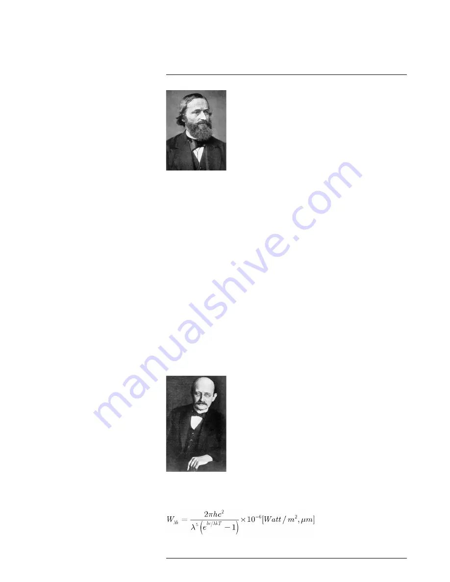
Figure 25.2
Gustav Robert Kirchhoff (1824–1887)
The construction of a blackbody source is, in principle, very simple. The radiation charac-
teristics of an aperture in an isotherm cavity made of an opaque absorbing material rep-
resents almost exactly the properties of a blackbody. A practical application of the
principle to the construction of a perfect absorber of radiation consists of a box that is
light tight except for an aperture in one of the sides. Any radiation which then enters the
hole is scattered and absorbed by repeated reflections so only an infinitesimal fraction
can possibly escape. The blackness which is obtained at the aperture is nearly equal to
a blackbody and almost perfect for all wavelengths.
By providing such an isothermal cavity with a suitable heater it becomes what is termed
a
cavity radiator
. An isothermal cavity heated to a uniform temperature generates black-
body radiation, the characteristics of which are determined solely by the temperature of
the cavity. Such cavity radiators are commonly used as sources of radiation in tempera-
ture reference standards in the laboratory for calibrating thermographic instruments,
such as a FLIR Systems camera for example.
If the temperature of blackbody radiation increases to more than 525°C (977°F), the
source begins to be visible so that it appears to the eye no longer black. This is the incipi-
ent red heat temperature of the radiator, which then becomes orange or yellow as the
temperature increases further. In fact, the definition of the so-called
color temperature
of
an object is the temperature to which a blackbody would have to be heated to have the
same appearance.
Now consider three expressions that describe the radiation emitted from a blackbody.
25.3.1
Planck’s law
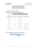
Figure 25.3
Max Planck (1858–1947)
Max Planck
(1858–1947) was able to describe the spectral distribution of the radiation
from a blackbody by means of the following formula:
#T559950; r. AD/35720/35720; en-US
95
Summary of Contents for A615
Page 1: ...User s manual FLIR A6xx series...
Page 2: ......
Page 3: ...User s manual FLIR A6xx series T559950 r AD 35720 35720 en US iii...
Page 4: ......
Page 8: ......
Page 71: ...Mechanical drawings 16 T559950 r AD 35720 35720 en US 63...
Page 81: ...CE Declaration of conformity 17 T559950 r AD 35720 35720 en US 73...
Page 82: ......
Page 84: ...Digital I O connection diagrams 19 T559950 r AD 35720 35720 en US 76...
Page 85: ......


