background image

8

ARMASIGHT by FLIR

SPARK       

U S E R   M A N U A L

SECTION 2

DESCRIPTION AND DATA

2.1  SYSTEM DESCRIPTION

The Spark is a hand-held, head-mounted, helmet-mounted, or weapon-mounted night vision system 

that allows the user to operate it while walking, firing weapons, conducting short-range surveillance, 

reading maps, conducting vehicle maintenance, or administering first aid in both moonlight and starlight 

conditions.
The Spark utilizes the principle of intensification of the residual light that is reflected from the 

surrounding objects. The optical system of the unit consists of an objective lens, an intensifier tube (IT), 

and an eyepiece.
Exclusive CORE (Ceramic Optical Ruggedized Engine) technology image intensifier tubes are used in the 

Spark monoculars. While CORE does not contain a micro channel plate (and so by definition lands in the 

Gen 1 category) that is where the parallels end. Instead of glass, CORE tubes use a specially formulated 

ceramic compound fused with metal alloys similar to those used in production of Gen 2 and Gen 3 image 

intensifier tubes. Further advances in CORE have almost removed edge distortion, dramatically increased 

photo-sensitivity and most importantly, almost doubled resolution up to 70 lp/mm. 
A built-in IR illuminator makes it possible to use the unit in low light or total darkness.
The Spark allows for vertical and fore-and-aft adjustment when mounted to the user’s head or helmet, 

when focusing the lens, and when focusing the eyepiece.

NOTE:

The equipment requires some light (moonlight, starlight, etc.) to operate. Performance of the device 

depends upon the level of ambient light in the environment. Please remember the following:

–  The level of ambient light in the environment is reduced by the presence of clouds, shade, or 

objects that block natural light (trees, buildings, etc.

–  The equipment is less effective when operated in shadows and other darkened areas.
–  The equipment is less effective when operated in rain, fog, sleet, snow, or smoke.
–  Under starlight conditions, particularly in low-contrast environments such as snow-covered 

territory, sandy deserts, large bodies of water or grassy hills, the visibility may degrade, 

thereby disguising or masking changes in terrain.

–  The equipment will not “see” through dense smoke.

Summary of Contents for ARMASIGHT

Page 1: ...U S E R M A N U A L ARMASIGHT by FLIR SPARK Night Vision Monocular...

Page 2: ...t is protected by patents design patents patents pending or design patents pending If you have questions that are not covered in this manual or need service contact FLIR OTS customer support for addit...

Page 3: ...ER Modification of this device without the express authorization of FLIR Commercial Systems Inc may void the user s authority under FCC rules to operate this device Note 1 This equipment has been test...

Page 4: ...ecifications 9 2 3 Standard Components 11 2 4 Optional Equipment 12 2 5 Key Features 14 3 OPERATING INSTRUCTIONS 15 3 1 Installation and Mounting 15 3 2 Controls 21 3 3 Operating Procedures 22 3 4 Sto...

Page 5: ...rom the unit infrared IR illuminator is invisible to the unaided eye when used in total darkness However the light can be detected by other Night Vision Devices NVD To reduce the risk of detection by...

Page 6: ...equipment with the battery still inserted Clean and dry each component of the Spark thoroughly before placing them in the storage case NOTES The equipment requires some ambient light moonlight starlig...

Page 7: ...lmet and is equipped with an infrared light emitting source IR illuminator 1 2 WARRANTY INFORMATION AND REGISTRATION 1 2 1 WARRANTY INFORMATION For warranty information and customer support visit www...

Page 8: ...2 and Gen 3 image intensifier tubes Further advances in CORE have almost removed edge distortion dramatically increased photo sensitivity and most importantly almost doubled resolution up to 70 lp mm...

Page 9: ...PMENT ITEM DIMENSIONS MM WEIGHT G Spark Night Vision Monocular 181 x 49 x 82 145 x 49 x 82 w o eyecup and lens cap 370 Flip up Helmet Mount 140 x 70 x 90 280 Goggle Kit 280 x 180 x 80 295 IR850 XLR 15...

Page 10: ...Focus Range 35 mm 1 1 7 0 25 m to infinity FOV with 1x Lens with 3x Afocal Lens with 5x Afocal Lens 35 11 30 7 30 Exit Pupil Diameter 8 mm Eye Relief 20 mm Eyepiece Diopter Adjustment 5 to 5 diopters...

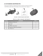
Page 11: ...ed in Table 2 6 The ITEM NO column indicates the number used to identify items in Figure 2 2 TABLE 2 6 SPARK STANDARD COMPONENTS ITEM NO DESCRIPTION QUANTITY 1 Night Vision Monocular 1 2 Lens Cap 1 3...

Page 12: ...ocal Lens Kit Lens 22 with Adapter 23 ANAF3X0023 5x A Focal Lens with Adapter 23 ANAF5X0023 ARFS3 ANAMRF0003 ARFS5 ANAMRF0005 Goggle Kit 1 ANHG000001 Helmet Mount 3 ANHM000002 Helmet Mount 170 Shroud...

Page 13: ...R SPARK U S E R M A N U A L IMAGE DESCRIPTION PART NO IR850 XLR Doubler ANAF18XLRM Extended Rail Adapter 85 ANAM000045 Universal Camera Adapter 45 ANAM000006 Hard Shipping Storage Case 101 ANHC000001...

Page 14: ...ht Compact and robust design Easy to operate Serviceability under severe conditions High performance Highly reliable Powered by single CR123 battery Head or helmet mountable for hands free usage Weapo...

Page 15: ...lows 1 Unscrew the battery cap A and insert the CR123A battery B observing the polarity markings on the body of the device 2 Screw the battery cap A back on securely 3 1 2 MOUNTING THE SPARK TO A GOGG...

Page 16: ...ition is reached To remove the Spark from the goggle kit loosen the screw A push the button B and slide the unit out of the bracket guide C 3 1 3 MOUNTING THE SPARK TO A HELMET An optional flip up hel...

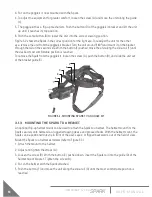
Page 17: ...unit along the slide rail G until the most comfortable position is reached To remove the Spark from the helmet mount loosen the screw B push down on the button C and slide the unit out of the guide D...

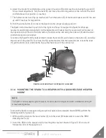
Page 18: ...s makes the nut D get back into its hollow Check to ensure the clamping device holds weapon NVM rail firmly 4 While pushing down on the lever holder F turn the lever E forward 5 Install the Spark on t...

Page 19: ...ntil its alignment boss is in line with the alignment groove on the helmet headgear assembly mount Push down until the Spark locks into the helmet headgear assembly mount To dismount the Spark from th...

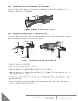
Page 20: ...w the adapter onto the tripod 2 Remove the eyecup from the Spark eyepiece 3 Install the Spark on the adapter rail A and tighten the fixing screw B 4 Install the camera on the adapter rail C and insert...

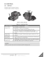
Page 21: ...vated Activate the IR illuminator by turning the switch CW from ON to the IR position Eyepiece Ring Figure 3 9 B Adjusts the unit diopter The total dioptric range is covered in a 1 2 ring revolution F...

Page 22: ...r light Fig 3 9 D indicates that the unit is ready for operation After a slight delay a green glow will appear in the eyepiece of the monocular 5 Adjust the unit diopter by rotating the ring of the ey...

Page 23: ...the scope lens Remove the unit by following the mounting instructions in reverse 4 Unscrew the battery cap and take out the battery Replace the battery cap Do not store the unit with the battery still...

Page 24: ...the location and the item to be checked or serviced PROCEDURE column Details the checking servicing procedure NOT FULLY MISSION CAPABLE IF column Indicates what faults will prevent your equipment fro...

Page 25: ...tate the eyepiece ring to make sure the eyepiece is not too tight or too loose Range is approximately turn Ring gets stuck is too loose or adversely affects the user s ability to properly adjust the d...

Page 26: ...Defective image intensifier Please contact Customer Support IR illuminator fails to activate Turn the IR illuminator on in a dark area Visually estimate whether or not the observed scene is illuminate...

Page 27: ...ll show up if edge glow occurs please contact Customer Support C Flashing Flickering or Intermittent Operation The image may appear to flicker or flash If there is more than a single flicker check for...

Page 28: ...urn the Spark Verify that emission points are not simply light sources present in the scene you are observing Emission points are acceptable if they do not interfere with the user s ability to perform...

Page 29: ...dry cloth 4 Using a lens brush carefully remove all loose dirt from the glass surfaces 5 Slightly dampen a cotton swab with ethanol Gently and slowly wipe the lenses Without touching the lens holders...

Page 30: ...sed by the manufacturer to identify an item this number controls the design and characteristics of the item by means of its engineering specifications standards and inspection requirements TABLE A 1 S...

Page 31: ...31 ARMASIGHT by FLIR SPARK U S E R M A N U A L...

Page 32: ...ernational Sales and Export OTS Export flir com Technical Support Repairs Returns Refunds Warranty OTS Support flir com www flir com www armasight com Equipment described herein is subject to US expor...

Reviews: