5
Operation
1.
Set the function switch to the
position.
2.
Insert the black probe lead into the negative
terminal and the red probe
lead into one of the following positive terminals:
•
for high current measurements.
•
for low current measurements.
3.
Use the
button to select AC, DC, or AC+DC voltage measurement.
•
The
indicator will be displayed for AC measurements.
•
The
indicator will be displayed for DC measurements.
•
The
indicator will be displayed for AC+DC measurements.
4.
Connect the probe leads in series with the part in accordance with Figure
5.1.
5.
Read the current value on the display.
5.11
Extended functionality
In addition to the basic measurements, the meter can be set to different modes
for extended functionality.
5.11.1
Selecting the mode
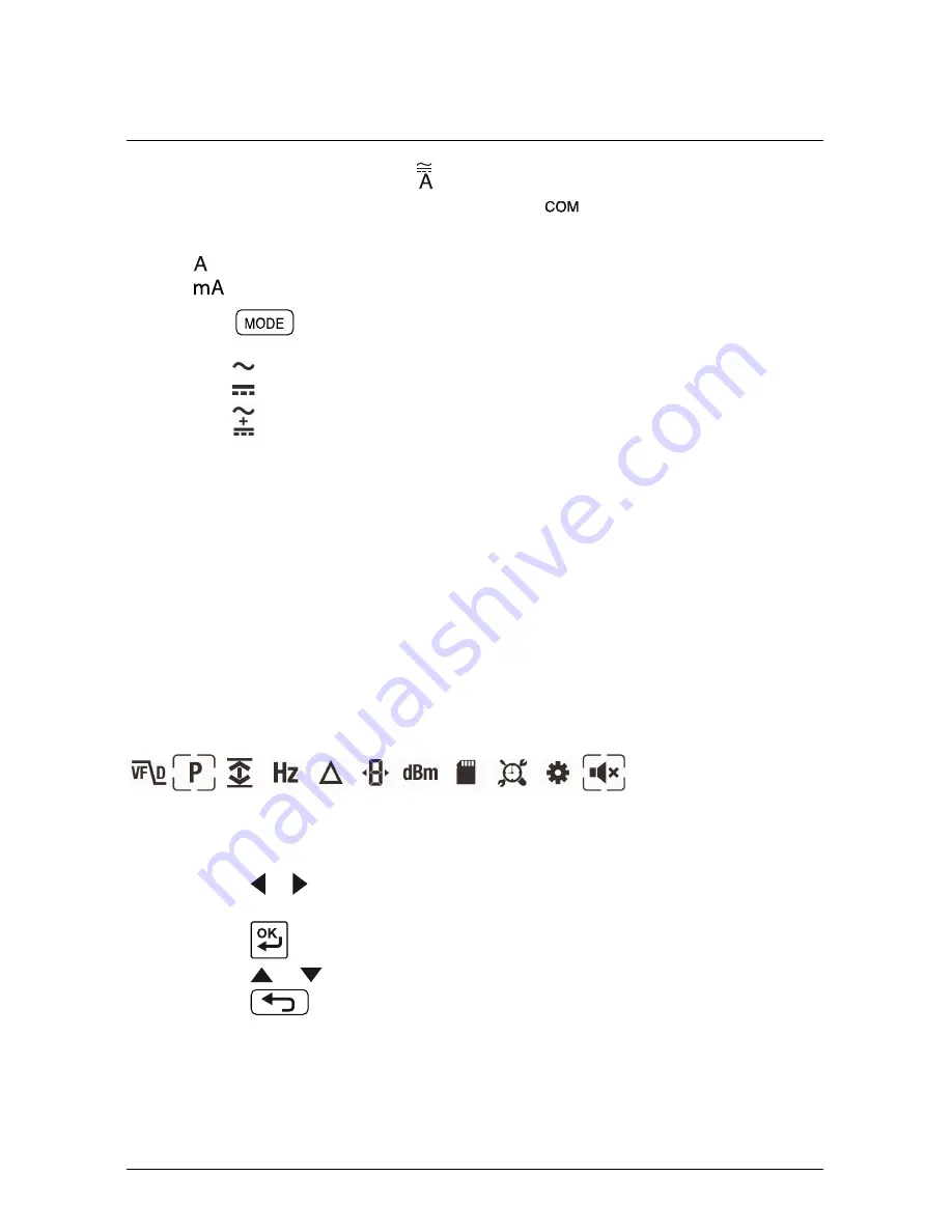
The mode icons applicable for the selected measurement type are displayed in
the lower part of the display. When a mode is enabled, the icon is framed.
Figure 5.2
Mode icons (AC voltage measurements): Peak mode and Silent
mode are enabled
1.
Press the
or
button to navigate to the desired mode icon. The currently
selected icon will flash.
2.
Press the
button to enable the selected (flashing) mode.
3.
Press the
or
button to step through the mode options.
4.
Press the
button to disable the selected (flashing) mode.
#T559824; r.8007/8011; en-US
18
Final
before
translation
Summary of Contents for DM93
Page 1: ...User s manual Flir DM93 Digital multimeter F i n a l b e f o r e t r a n s l a t i o n...
Page 2: ...F i n a l b e f o r e t r a n s l a t i o n...
Page 3: ...User s manual Flir DM93 T559824 r 8007 8011 en US F i n a l b e f o r e t r a n s l a t i o n...
Page 4: ...F i n a l b e f o r e t r a n s l a t i o n...
Page 39: ...F i n a l b e f o r e t r a n s l a t i o n...
Page 42: ......


