427-0101-01-12 Revision 100
September 2020
12
This document does not contain any export-controlled information.
Installation
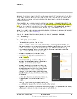
Step 2
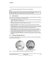
The wall mount bracket is shipped attached to the back box. Using the screwdriver,
unscrew the three quarter-turn twist-lock screws to release the wall mount bracket.
Step 3
Using the appropriate screw holes marked on the wall mount bracket, secure it to the
electrical box.
2.5
Connecting the Radar and Installing the Back Box
When mounted, all of the radar’s connections are made inside the back box. The radar assembly
plugs into the back box.
Power
The radar can be powered by Power over Ethernet (PoE) or with a conventional 24 VAC or 12 VDC
power supply. The Elara Radar is a Powered Device compliant with the IEEE 802.3af-2003
standard. To use PoE, connect the radar to either a IEEE 802.3af-2003 standard PoE switch or a
PoE injector.
The maximum Ethernet cable run is 100 meters, including the PoE power supply. Installations using
PoE and IP video only require a single Ethernet cable connection.
Grounding
Ensure the radar is properly grounded. Failure to properly ground it can lead to permanent damage
to the radar. Typical to good grounding practices, the radar back box chassis ground should be
connected to the lowest resistance path possible.
To connect the Elara Radar and install the back box:
Step 1
Ensure the power supply or circuit breaker is off.
Step 2
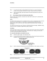
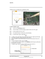
For each cable, use the Torx wrench to punch a hole in the center of the grommet from the
underside. Insert the cable from the conduit though the hole.
Step 3
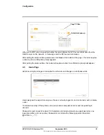
Push the cable back through the seal so the seal extends out of the back box, as shown:
Step 4
Seal all exposed connections. Cable connections are not waterproof.
Punch through grommet
from underside here
For wall mount,
attach cover using
Torx wrench
Wrong
Correct
Inside back box


