background image

EX510-EU-EN-V3.3-1/12 

9

FREQUENCY/DUTY CYCLE MEASUREMENTS (ELECTRONIC) 

1. Set the rotary function switch to the green “

Hz %

” position. 

2. Press the Hz/% button to indicate “

Hz

” in the display. 

3. Insert the black lead banana plug into the negative 

COM

 jack and the red 

test lead banana plug into the positive 

Hz

 jack. 

4. Touch the test probe tips to the circuit under test. 
5. Read the frequency on the display. 
6. Press the 

Hz/%

 button again to indicate “

%

” on the display. 

7. Read the % of duty cycle on the display. 


AUTORANGING/MANUAL RANGE SELECTION 

When the meter is first turned on, it automatically goes into Autoranging. This automatically selects 
the best range for the measurements being made and is generally the best mode for most 
measurements. For measurement situations requiring that a range be manually selected, perform 
the following: 

1. Press  the

 RANGE

 key. The “

AUTO”

 display indicator will turn off. 

2. Press  the 

RANGE

 key to step through available ranges until you select the desired range. 

3. To exit the Manual Ranging mode and return to Autoranging, press and hold the

 RANGE

 key for 2 

seconds. 

Note:

 Manual ranging does not apply for the Capacitance and Frequency functions. 

MAX/MIN 

 Note:

 When using the MAX/MIN function in Autoranging mode, the meter will “lock” into the range 

that is displayed on the LCD when MAX/MIN is activated. If a MAX/Min reading exceeds that 
range, an “OL” will be displayed. Select the desired range BEFORE entering MAX/MIN mode. 

1. Press the 

MAX/MIN

 key to activate the MAX/MIN recording mode. The display icon "

MAX

" will 

appear. The meter will display and hold the maximum reading and will update only when a new 
“max” occurs. 

2. Press  the 

MAX/MIN

 key again and the display icon "

MIN

" will appear. The meter will display and 

hold the minimum reading and will update only when a new “min” occurs. 

3. To exit MAX/MIN mode press and hold the 

MAX/MIN

 key for 2 seconds. 

RELATIVE MODE 

The relative measurement feature allows you to make measurements relative to a stored reference 
value. A reference voltage, current, etc. can be stored and measurements made in comparison to 
that value. The displayed value is the difference between the reference value and the measured 
value. 

1. Perform the measurement as described in the operating instructions. 
2. Press the 

REL

 button to store the reading in the display and the "

REL

" indicator will appear on the 

display. 

3. The display will now indicate the difference between the stored value and the measured value. 
4. Press the 

REL

 button to exit the relative mode. 

Note:

 The Relative function does not operate in the Frequency function. 

Summary of Contents for Extech EX510

Page 1: ...User s Guide Industrial Multimeter Extech EX510...

Page 2: ...ing associated with ranges that may in normal use be subjected to particularly hazardous voltages For maximum safety the meter and its test leads should not be handled when these terminals are energiz...

Page 3: ...ets can be difficult and misleading because of the uncertainty of connection to the recessed electrical contacts Other means should be used to ensure that the terminals are not live If the equipment i...

Page 4: ...g with high voltages 3 DO NOT measure voltage if the voltage on the COM input jack exceeds 600V above earth ground 4 NEVER connect the meter leads across a voltage source while the function switch is...

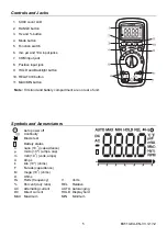
Page 5: ...MIN button Note Tilt stand and battery compartment are on rear of unit Symbols and Annunciators Auto power off Continuity Diode test Battery status n nano 10 9 capacitance micro 10 6 amps cap m milli...

Page 6: ...he display AC VOLTAGE FREQUENCY DUTY CYCLE MEASUREMENTS WARNING Risk of Electrocution The probe tips may not be long enough to contact the live parts inside some 240V outlets for appliances because th...

Page 7: ...AC CURRENT FREQUENCY DUTY CYCLE MEASUREMENTS CAUTION Do not make 20A current measurements for longer than 30 seconds Exceeding 30 seconds may cause damage to the meter and or the test leads 1 Insert b...

Page 8: ...continuity on circuits or wires that have voltage on them 1 Set the function switch to the green CAP position 2 Insert the black lead banana plug into the negative COM jack Insert the red test lead ba...

Page 9: ...using the MAX MIN function in Autoranging mode the meter will lock into the range that is displayed on the LCD when MAX MIN is activated If a MAX Min reading exceeds that range an OL will be displayed...

Page 10: ...reading in the display Press the HOLD key momentarily to activate or to exit the HOLD function AUTO POWER OFF The auto off feature will turn the meter off after 15 minutes To disable the auto power o...

Page 11: ...LY FRESH BATTERIES OF THE RECOMMENDED SIZE AND TYPE Remove old or weak batteries so they do not leak and damage the unit 6 IF THE METER IS TO BE STORED FOR A LONG PERIOD OF TIME the batteries should b...

Page 12: ...e cover 1 Disconnect the test leads from the meter 2 Remove the protective rubber holster 3 Remove the battery cover two B screws and the battery 4 Remove the six A screws securing the rear cover 5 Ge...

Page 13: ...ranges are specified from 5 of range to 100 of range 600 A 0 1 A 6000 A 1 A 60mA 0 01mA 600mA 0 1mA 6A 0 001A 10A 0 01A 1 0 reading 3 digits DC Current 20A 30 sec max with reduced accuracy 40Hz to 1kH...

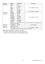
Page 14: ...Hz 0 01MHz 0 1 reading 1 digits Frequency electronic Sensitivity 0 8V rms min 20 to 80 duty cycle and 100kHz 5Vrms min 20 to 80 duty cycle and 100kHz 10 00 400Hz 0 01Hz 0 5 reading Frequency electrica...

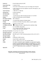
Page 15: ...voltage Battery One 9 volt NEDA 1604 battery Fuses mA A ranges 0 8A 1000V ceramic fast blow A range 10A 1000V ceramic fast blow Operating Temperature 5 C to 40 C 41 F to 104 F Storage Temperature 20...

Reviews: