background image

17.5

Different types of hot spots in electrical installations

17.5.1

Reflections

The thermographic camera sees any radiation that enters the lens, not only originating
from the object that you are looking at, but also radiation that comes from other
sources and has been reflected by the target. Most of the time, electrical components
are like mirrors to the infrared radiation, even if it is not obvious to the eye. Bare
metal parts are particularly shiny, whereas painted, plastic or rubber insulated parts
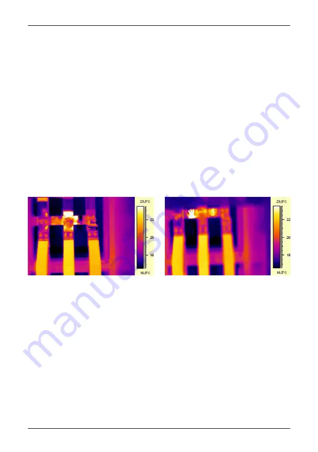
are mostly not. In the image below, you can clearly see a reflection from the thermo-
grapher. This is of course not a hot spot on the object. A good way to find out if what
you see is a reflection or not, is for you to move. Look at the target from a different
angle and watch the ‘hot spot.’ If it moves when you do, it is a reflection.

Measuring temperature of mirror like details is not possible. The object in the images
below has painted areas which are well suited for temperature measurement. The
material is copper, which is a very good heat conductor. This means that temperature
variation over the surface is small.

10717503;a2

Figure 17.11 Reflections in an object

17.5.2

Solar heating

The surface of a component with a high emissivity, for example, a breaker, can on a
hot summer day be heated up to quite considerable temperatures by irradiation from
the sun. The image shows a circuit breaker, which has been heated by the sun.

108

Publ. No. T559382 Rev. a358 – ENGLISH (EN) – June 23, 2009

17 – Introduction to thermographic inspections of electrical installations

Summary of Contents for Extech i5

Page 1: ...živatelská příručka Gebruikershandleiding User s manual Benutzerhandbuch Manual del usuario Manuel de l utilisateur Manuale dell utente Manual do utilizador Felhas ználói kézikönyv Käyttäjän opas Betjeningsvejledning Brukerveiledning Instrukcja obsługi Bruksanvisning Kullanım Kılavuzu Uživatelská příručka Gebruikershandleiding User s manual FLIR i5 FLIR i7 T559382 Publ No a358 Revision English EN ...

Page 2: ......

Page 3: ...User s manual Publ No T559382 Rev a358 ENGLISH EN June 23 2009 ...

Page 4: ...ks or trademarks of FLIR Systems and or its subsidiaries All other trademarks trade names or company names referenced herein are used for identification only and are the property of their respective owners Quality assurance The Quality Management System under which these products are developed and manufactured has been certified in accordance with the ISO 9001 standard FLIR Systems is committed to...

Page 5: ...FIFTY DOLLARS U S 250 00 Limitations on Reverse Engineering Decompilation and Disassembly You may not reverse engineer decompile or disassemble the SOFTWARE except and only to the extent that such activity is expressly permitted by applicable law notwithstanding this limitation SOFTWARE TRANSFER ALLOWED BUT WITH RESTRICTIONS You may permanently transfer rights under this EULA only as part of a per...

Page 6: ...vi Publ No T559382 Rev a358 ENGLISH EN June 23 2009 ...

Page 7: ...otmeter 25 11 9 Measuring a temperature using an area 26 11 10 Marking all areas above or below a set temperature level 27 11 11 Changing the color palette 28 11 12 Changing the settings 29 11 13 Changing the image mode 30 11 14 Setting the surface properties 31 11 15 Changing the emissivity 32 11 16 Changing the reflected apparent temperature 33 11 17 Resetting the camera 34 11 18 Finding the ser...

Page 8: ...s balconies 59 16 2 5 1 General information 60 16 2 5 2 Commented building structures 62 16 2 5 3 Commented infrared images 62 16 2 6 Moisture detection 4 Plumbing breaks leaks 62 16 2 6 1 General information 63 16 2 6 2 Commented infrared images 65 16 2 7 Air infiltration 65 16 2 7 1 General information 65 16 2 7 2 Commented building structures 67 16 2 7 3 Commented infrared images 68 16 2 8 Insu...

Page 9: ...mparative measurement 103 17 3 4 Normal operating temperature 104 17 3 5 Classification of faults 106 17 4 Reporting 108 17 5 Different types of hot spots in electrical installations 108 17 5 1 Reflections 108 17 5 2 Solar heating 109 17 5 3 Inductive heating 109 17 5 4 Load variations 110 17 5 5 Varying cooling conditions 111 17 5 6 Resistance variations 111 17 5 7 Overheating in one part as a re...

Page 10: ...1 20 6 Other parameters 132 21 History of infrared technology 136 22 Theory of thermography 136 22 1 Introduction 136 22 2 The electromagnetic spectrum 137 22 3 Blackbody radiation 138 22 3 1 Planck s law 139 22 3 2 Wien s displacement law 141 22 3 3 Stefan Boltzmann s law 142 22 3 4 Non blackbody emitters 144 22 4 Infrared semi transparent materials 146 23 The measurement formula 152 24 Emissivit...

Page 11: ...t can become hot and cause an explosion or ignition Only use the correct equipment to discharge the battery If you do not use the correct equipment you can decrease the performance or the life cycle of the battery If you do not use the correct equipment an incorrect flow of current to the battery can occur This can cause the battery to become hot or cause an explosion and injury to persons Make su...

Page 12: ...your sales office if one or more of these problems occurs Only use a specified battery charger when you charge the battery The temperature range through which you can charge the battery is 0 C to 45 C 32 F to 113 F If you charge the battery at temperatures out of this range it can cause the battery to become hot or to break It can also decrease the performance or the life cycle of the battery The ...

Page 13: ...tion once a year Contact your local sales office for instructions on where to send the camera Accuracy This notice only applies to cameras with measurement capabilities For very accurate results we recommend that you wait 5 minutes after you have started the camera before measuring a temperature For cameras where the detector is cooled by a mechanical cooler this time period excludes the time it t...

Page 14: ...e that you have the following informa tion to hand The camera model The camera serial number The communication protocol or method between the camera and your PC for example HDMI Ethernet USB or FireWire Operating system on your PC Microsoft Office version Full name publication number and revision number of the manual Downloads On the customer help site you can also download the following Firmware ...

Page 15: ...basis To access the latest manuals and notifications go to the Download tab at http flir custhelp com It only takes a few minutes to register online In the download area you will also find the latest releases of manuals for our other products as well as manuals for our historical and obsolete products Publ No T559382 Rev a358 ENGLISH EN June 23 2009 5 ...

Page 16: ... this manual may contain descriptions and explanations that do not apply to your particular camera model NOTE FLIR Systems reserves the right to discontinue models software parts or accessories and other items or to change specifications and or functionality at any time without prior notice 6 Publ No T559382 Rev a358 ENGLISH EN June 23 2009 ...

Page 17: ...t time Charge the battery by connecting the power supply to the power connector on the camera Make sure that you use the correct AC plug Note The first time you charge a factory new battery you must turn on and then turn off the camera after you have connected the power supply to the power connector on the camera T630175 a1 1 Battery charging indicator 2 Power supply cable 2 Insert a miniSD memory...

Page 18: ...ever T630177 a1 5 Aim the camera toward your target of interest 6 Pull the Save trigger to save the image 7 To move the image to a computer do one of the following T630178 a1 Fig 1 above Remove the miniSD memory card and insert it into a card reader connected to a computer A miniSD card adapter is includ ed with your camera Fig 2 above Connect a computer to the camera using a USB Mini B cable 8 In...

Page 19: ...tarted Guide USB cable User documentation CD ROM NOTE Contact your local sales office if any item is damaged or missing You can find the addresses and telephone numbers of local sales offices on the back cover of this manual FLIR Systems reserves the right to discontinue models parts or accessories and other items or to change specifications at any time without prior notice Publ No T559382 Rev a35...

Page 20: ...figure above Infrared lens 1 Lever to open and close the lens cap 2 Trigger to save images 3 Cover to connectors and the miniSD memory card slot 4 Cover to the battery compartment 5 Attachment point for the hand strap 6 10 Publ No T559382 Rev a358 ENGLISH EN June 23 2009 ...

Page 21: ...ush to navigate in the image archive 2 Left selection button This button is context sensitive and the current function is displayed above the button on the screen 3 button on the navigation pad Function Push to go up in menus submenus and dialog boxes Push to display the image archive after having pushed the Archive button Push to increase change the value 4 Publ No T559382 Rev a358 ENGLISH EN Jun...

Page 22: ... sensitive and the current function is displayed above the button on the screen 6 On Off button Function Push to turn on the camera Push and hold down for more than one second to turn off the camera 7 button on navigation pad Function Push to go down in menus submenus and dialog boxes Push to decrease change the value 8 12 Publ No T559382 Rev a358 ENGLISH EN June 23 2009 8 Camera parts ...

Page 23: ...or Meaning Icon One of the following The camera is powered using the battery The battery is being charged indicated by a refilling battery animation The battery is fully charged and the camera is powered using the power supply 3 Date and time 4 Limit value for the temperature scale 5 Publ No T559382 Rev a358 ENGLISH EN June 23 2009 13 ...

Page 24: ...urrently set emissivity value or material properties 7 Current function for the right selection button 8 Current function for the left selection button 9 14 Publ No T559382 Rev a358 ENGLISH EN June 23 2009 9 Screen elements ...

Page 25: ...0 images saving more than that number of images severely slows down file manage ment on the miniSD memory card Note There is no upper limit to the memory size of the miniSD memory card 1 Battery charging indicator No light The power supply is not connected Orange light The battery is being charged Green light The charging of the battery is completed 2 Power supply cable 3 USB cable with USB Mini B...

Page 26: ...ompartment cover T630174 a1 1 Connect the cable that is attached to the battery to the connector inside the battery compartment Note Do not use conductive tools when doing this T630173 a2 2 Push the battery into place 3 Replace the cover to close the battery compartment 4 16 Publ No T559382 Rev a358 ENGLISH EN June 23 2009 ...

Page 27: ...ery connector inside the battery compartment Then press the On Off button again The reset button T630179 a1 Do not replace the battery on a frequent basis Only replace the battery when it is worn out About the battery charging indicator The battery charging indicator is an LED beside the power connector It displays the following signals No light The power supply is not connected Orange light The b...

Page 28: ...ty plug to a mains socket Make sure that you use the correct AC plug 2 Disconnect the power supply cable plug when the battery charging indicator displays a green light 3 18 Publ No T559382 Rev a358 ENGLISH EN June 23 2009 11 Using the camera ...

Page 29: ...the FAT FAT16 file system Using FAT32 formatted memory cards may result in inferior performance To format a memory card to FAT FAT16 follow this procedure Insert the memory card into a card reader that is connected to your com puter 1 In Windows Explorer select My Computer and right click the memory card 2 Select Format 3 Under File system select FAT 4 Click Start 5 Naming convention The naming co...

Page 30: ...ge Push the Archive button 1 Do one of the following Push the navigation pad left right to select the image you want to view Push the button use the navigation pad to select the image you want to see then push the right selection button Open 2 To return to live mode do one of the following Push the Archive button Push the right selection button Close 3 20 Publ No T559382 Rev a358 ENGLISH EN June 2...

Page 31: ... this procedure to open the image archive Push the Archive button 1 Push the button on the navigation pad This will display the image archive You can now use the navigation pad to navigate in the archive 2 To open a selected image push the right selection button Open 3 Publ No T559382 Rev a358 ENGLISH EN June 23 2009 21 11 Using the camera ...

Page 32: ...ion button Select 6 Push the right selection button to confirm Delete 7 To return to live mode do one of the following Push the Archive button Push the right selection button Close 8 Alternative 2 Follow this procedure to delete an image Push the Archive button 1 Select the image you want to delete by using the navigation pad 2 Push the left selection button Delete 3 Push the right selection butto...

Page 33: ...s Push the Archive button 1 Push the button This will display the image archive 2 Push the left selection button Options 3 Use the navigation pad to select Delete all images 4 Push the left selection button Select 5 Push the right selection button to confirm Delete 6 Publ No T559382 Rev a358 ENGLISH EN June 23 2009 23 11 Using the camera ...

Page 34: ...ow this procedure Push the left selection button Menu 1 Use the navigation pad to select Measurement 2 Push the left selection button Select 3 Use the navigation pad to select Spot 4 Push the left selection button Select The temperature at the position of the spotmeter will now displayed in the top left corner of the screen 5 24 Publ No T559382 Rev a358 ENGLISH EN June 23 2009 11 Using the camera ...

Page 35: ...navigation pad to select Measurement 2 Push the left selection button Select 3 Use the navigation pad to select one of the following Area max Area min 4 Push the left selection button Select The highest or lowest temperature within the area will now be indicated by a continuously moving cursor The temperature will also be displayed in the top left corner of the screen 5 Publ No T559382 Rev a358 EN...

Page 36: ...on Menu 1 Use the navigation pad to select Measurement 2 Push the left selection button Select 3 Use the navigation pad to select one of the following Detect above Detect below 4 Push the left selection button Select 5 To change the temperature level above or below which you want to mark the areas use the navigation pad 6 26 Publ No T559382 Rev a358 ENGLISH EN June 23 2009 11 Using the camera ...

Page 37: ...edure to change the color palette Push the left selection button Menu 1 Use the navigation pad to go to Color palette 2 Push the left selection button Select This will display the Color palette submenu 3 Use the navigation pad to select the new color palette 4 Push the left selection button Select to confirm the choice and leave the submenu 5 Publ No T559382 Rev a358 ENGLISH EN June 23 2009 27 11 ...

Page 38: ...e a setting Push the left selection button Menu 1 Use the navigation pad to go to Settings 2 Push the left selection button Select This will display the Settings sub menu 3 Use the navigation pad to select the setting you want to change 4 Push the left selection button Select then use the navigation pad to select a new setting 5 Push the left selection button Select to confirm the choice and leave...

Page 39: ...king for temperature anomalies in two items of similar design or construction For example if you are looking at two cables where you suspect one is overheated working in Locked mode will clearly show that one is overheated The higher temper ature in that cable would create a lighter color for the higher temperature If you use Auto mode instead the color for the two items will appear the same Proce...

Page 40: ...Push the left selection button Menu 1 Use the navigation pad to go to Measure 2 Push the left selection button Select This will display the Measure sub menu 3 On the Measure menu use the navigation pad to select a surface property 4 Push the left selection button Select to confirm the choice and leave the menu 5 SEE ALSO For more precise measurements see the following sections Section 11 15 Changi...

Page 41: ...ty of 0 14 while a structured PVC floor typically has an emissivity of 0 93 Procedure Follow this procedure to set the emissivity Push the left selection button Menu 1 Use the navigation pad to go to Measure 2 Push the left selection button Select This will display the Measure sub menu 3 Use the navigation pad to select Advanced 4 Push the left selection button Select This will display the Advance...

Page 42: ...eft selection button Menu 1 Use the navigation pad to go to Measure 2 Push the left selection button Select This will display the Measure sub menu 3 Use the navigation pad to select Advanced 4 Push the left selection button Select This will display the Advanced sub menu 5 Use the navigation pad to set the reflected apparent temperature 6 Push the left selection button Select to confirm the choice ...

Page 43: ...l or other conductive tool to reset the camera Procedure Follow this procedure to reset the camera Open the battery compartment cover 1 To locate the reset button see the figure below T630179 a1 2 Use a non conductive tool to push reset button The camera will now be reset 3 Publ No T559382 Rev a358 ENGLISH EN June 23 2009 33 11 Using the camera ...

Page 44: ...you communicate with our service departments you may need to state the serial number of the camera The serial number is printed on a label inside the battery compartment behind the battery 34 Publ No T559382 Rev a358 ENGLISH EN June 23 2009 11 Using the camera ...

Page 45: ...olution Equipment A soft cloth Procedure Follow this procedure Soak the cloth in the liquid 1 Twist the cloth to remove excess liquid 2 Clean the part with the cloth 3 CAUTION Do not apply solvents or similar liquids to the camera the cables or other items This can cause damage Publ No T559382 Rev a358 ENGLISH EN June 23 2009 35 ...

Page 46: ...an the lens one time only and discard the cotton wool 3 WARNING Make sure that you read all applicable MSDS Material Safety Data Sheets and warning labels on containers before you use a liquid the liquids can be dangerous CAUTION Be careful when you clean the infrared lens The lens has a delicate anti reflective coating Do not clean the infrared lens too vigorously This can damage the anti reflect...

Page 47: ...pixels FLIR i5 2009 model 120 120 pixels FLIR i7 IR resolution Image presentation Display 2 8 in color LCD Automatic adjust lock image Image adjustment Measurement Object temperature range 0 C to 250 C 32 to 482 F 2 C 3 6 F or 2 of reading for ambient temper ature 10 C to 35 C 50 F to 95 F Accuracy Measurement analysis Spotmeter Center spot Dependent on the camera Not applicable FLIR i5 2009 model...

Page 48: ...ge Approx 5 hours at 25 C 77 F ambient tempera ture and typical use Battery operating time Battery is charged inside the camera Charging system 3 h to 90 capacity Charging time Automatic shut down Power management AC adapter 90 260 VAC input 5 V output to camera AC operation Environmental data Operating temperature range 0 C to 50 C 32 F to 122 F 40 C to 70 C 40 F to 158 F Storage temperature rang...

Page 49: ... Color Certifications Certification UL CSA CE PSE and CCC Scope of delivery Packaging type Hard case FLIR QuickReport CD Printed Getting Started Guide User documentation CD ROM Calibration certificate Hand strap Battery inside camera Power supply charger with EU UK US and Aus tralian plugs USB cable miniSD card 512 MB with SD card adapter Packaging contents Publ No T559382 Rev a358 ENGLISH EN June...

Page 50: ...VFOV vertical field of view 3 HFOV horizontal field of view 4 IFOV instan taneous field of view size of one detector element This table gives examples of the field of view for different target distances Note The table does not take into account the minimum focus distance 10781103 a1 40 Publ No T559382 Rev a358 ENGLISH EN June 23 2009 13 Technical data ...

Page 51: ...cal field of view 3 HFOV horizontal field of view 4 IFOV instan taneous field of view size of one detector element This table gives examples of the field of view for different target distances Note The table does not take into account the minimum focus distance T638201 a1 Publ No T559382 Rev a358 ENGLISH EN June 23 2009 41 13 Technical data ...

Page 52: ...ower supply charger with EU UK US and AU plugs AC operation 100 240 V 50 60 Hz output 5 0 VAC 1 2 A 6 W Power 69 2 43 3 29 8 mm 2 7 1 7 1 2 in Size L W H 1 8 m 5 9 ft Cable length Power supply Battery charger EU UK US and Australian plugs Packaging contents Memory card 512 MB miniSD 512 MB Memory card size 21 5 20 1 4 mm 0 85 0 79 0 06 in Size L W H miniSD card Adapter from miniSD Card to SD Memor...

Page 53: ...14 Dimensions 14 1 Camera front Figure 10780603 a1 Publ No T559382 Rev a358 ENGLISH EN June 23 2009 43 ...

Page 54: ...14 2 Camera side Figure 10780703 a1 44 Publ No T559382 Rev a358 ENGLISH EN June 23 2009 14 Dimensions ...

Page 55: ...rs can come into play as to how moisture or water damage will appear in an infrared image For example heating and cooling of these parts takes place at different rates depend ing on the material and the time of day For this reason it is important that other methods are used as well to check for moisture or water damage Figure The image below shows extensive water damage on an external wall where t...

Page 56: ...ket s construction may differ dramatically from one manufacturer to another For this reason different faults in a socket can lead to the same typical appearance in an infrared image Local temperature increase can also result from improper contact between wire and socket or from difference in load Figure The image below shows a connection of a cable to a socket where improper contact in the connect...

Page 57: ...another For this reason different faults in a socket can lead to the same typical appearance in an infrared image Local temperature increase can also result from improper contact between a wire and socket or from difference in load Figure The image below shows a series of fuses where one fuse has a raised temperature on the contact surfaces against the fuse holder Because of the fuse holder s blan...

Page 58: ...me of the building NOTE When you are inspecting a building the temperature difference between the inside and outside should be at least 10 C 18 F Studs water pipes concrete columns and similar components may resemble an insulation deficiency in an infrared image Minor differences may also occur naturally Figure In the image below insulation in the roof framing is lacking Due to the absence of insu...

Page 59: ... house Close all doors windows and ventilation ducts and allow the kitchen fan to run for a while before you take the infrared images An infrared image of draft often shows a typical stream pattern You can see this stream pattern clearly in the picture below Also keep in mind that drafts can be concealed by heat from floor heating circuits Figure The image below shows a ceiling hatch where faulty ...

Page 60: ...between 0 85 and 0 95 Setting the emissivity value in the camera to 0 90 can be regarded as a good starting point An infrared inspection alone should never be used as a decision point for further actions Always verify suspicions and findings using other methods such as con struction drawings moisture meters humidity temperature datalogging tracer gas testing etc Change level and span to thermally ...

Page 61: ...dity levels above 50 can provide sufficient moisture to enable mold to grow 10556003 a1 Figure 16 2 Microscopic view of mold spore 16 2 1 3 Guidelines for detection of air infiltration insulation deficiencies For very accurate camera measurements take measurements of the temperature and enter this value in the camera It is recommended that there is a difference in pressure between the outside and ...

Page 62: ...Water remaining from firefighting As a non destructive detection method using an infrared camera has a number of advantages over other methods and a few disadvantages Disadvantage Advantage The method only detects surface temperature differentials and can not see through walls The method can not detect subsurface damage i e mold or structural damage The method is quick The method is a non intrusiv...

Page 63: ...ined in the table below from SPIE Thermosense Proceedings Vol 371 1982 p 177 Cause 47 6 Poor workmanship 2 6 Roof traffic 16 7 Poor design 7 8 Trapped moisture 8 0 Materials 8 4 Age weathering Potential leak locations include the following Flashing Drains Penetrations Seams Blisters 16 2 3 2 Safety precautions Recommend a minimum of two people on a roof preferably three or more Inspect the undersi...

Page 64: ...oofs Comment Structural drawing Inadequate sealing of roof membrane around conduit and ventilation ducts leading to local leakage around the conduit or duct 10553603 a2 Roof membrane inadequately sealed around roof access hatch 10553703 a2 54 Publ No T559382 Rev a358 ENGLISH EN June 23 2009 16 Introduction to building thermography ...

Page 65: ...roof When the surface itself is dry including any gravel or ballast a sunny day will warm the entire roof Early in the evening if the sky is clear the roof will begin to cool down by radiation Because of its higher thermal capacity the wet insulation will stay warmer longer than the dry and will be visible in the infrared camera see photos below The technique is partic ularly effective on roofs ha...

Page 66: ...ass its temperature decreas es slower than surrounding areas 10554003 a1 Water damaged roofing components and insula tion identified from infrared scan from the under side of the built up roof on a structural concrete tee deck Affected areas are cooler than the surrounding sound areas due to conductive and or thermal capacitive effect 10554103 a1 Daytime survey of built up low slope commercial roo...

Page 67: ...e test cuts 16 2 4 2 Commented building structures This section includes a few typical examples of moisture problems on commercial and residential façades Comment Structural drawing Pelting rain penetrates the façade due to badly executed bed joints Moisture builds up in the masonry above the window 10554303 a2 Pelting rain hits the window at an angle Most of the rain runs off the window edge flas...

Page 68: ...ater then follows the inside of the plaster and leads to frost erosion 10554503 a2 Rain splashes on the façade and penetrates the plaster and masonry by absorption which eventu ally leads to frost erosion 10554603 a2 58 Publ No T559382 Rev a358 ENGLISH EN June 23 2009 16 Introduction to building thermography ...

Page 69: ...ks balconies 16 2 5 1 General information Although there are differences in design materials and construction decks plaza decks courtyard decks etc suffer from the same moisture and leaking problems as low slope commercial roofs Improper flashing inadequately sealed membranes and insufficient drainage may lead to substantial damage in the building structures below Balconies although smaller in siz...

Page 70: ...es Comment Structural drawing Improper sealing of paving and membrane to roof outlet leading to leakage during rain 10555203 a2 No flashing at deck to wall connection leading to rain penetrating the concrete and insulation 10555103 a2 60 Publ No T559382 Rev a358 ENGLISH EN June 23 2009 16 Introduction to building thermography ...

Page 71: ...o concrete disintegration and corrosion of reinforcement SECURITY RISK 10555003 a2 Water has penetrated the plaster and underlying masonry at the point where the handrail is fastened to the wall SECURITY RISK 10554903 a2 Publ No T559382 Rev a358 ENGLISH EN June 23 2009 61 16 Introduction to building thermography ...

Page 72: ...re resulted in standing water between the structural concrete deck and the plaza wearing surface 10555403 a1 16 2 6 Moisture detection 4 Plumbing breaks leaks 16 2 6 1 General information Water from plumbing leaks can often lead to severe damage on a building structure Small leaks may be difficult to detect but can over the years penetrate structural walls and foundations to a degree where the bui...

Page 73: ...n nels inside ceiling of a single family home where a plumbing line had ruptured 10555503 a1 Water from plumbing leak was found to have mi grated farther than originally anticipated by the contractor during remediation techniques of cutting back carpet and installing dehumidifiers 10555603 a1 Publ No T559382 Rev a358 ENGLISH EN June 23 2009 63 16 Introduction to building thermography ...

Page 74: ...ows the path of a seri ous leak from a washing machine on the third floor which is completely hidden within the wall 10555703 a1 Water leak due to improper sealing between floor drain and tiles 10555803 a1 64 Publ No T559382 Rev a358 ENGLISH EN June 23 2009 16 Introduction to building thermography ...

Page 75: ... s 0 49 ft s are usually noticed by inhabitants although these air flows may be difficult to detect using ordinary measurement devices On an infrared image air infiltration can be identified by its typical ray pattern which emanates from the point of exit in the building structure e g from behind a skirting strip Furthermore areas of air infiltration typically have a lower detected temperature tha...

Page 76: ...he air infiltration enters the room from behind the cornice 10552303 a2 Air infiltration in a concrete floor over crawl space due to cracks in the brick wall façade The air infiltration enters the room beneath the skirting strip 10552603 a2 66 Publ No T559382 Rev a358 ENGLISH EN June 23 2009 16 Introduction to building thermography ...

Page 77: ...filtration from behind a skirting strip Note the typical ray pattern 10552703 a1 Air infiltration from behind a skirting strip Note the typical ray pattern The white area to the left is a radiator 10552803 a1 Air infiltration from behind a skirting strip Note the typical ray pattern 10552903 a1 Publ No T559382 Rev a358 ENGLISH EN June 23 2009 67 16 Introduction to building thermography ...

Page 78: ...are of the following parts in a building structure which may look like insulation deficiencies on the infrared image Wooden joists studs rafter beams Steel girders and steel beams Water piping inside walls ceilings floors Electrical installations inside walls ceilings floors such as trunking piping etc Concrete columns inside timber framed walls Ventilation ducts air ducts 16 2 8 2 Commented build...

Page 79: ...kind of insulation deficiency will show up as dark areas on an infrared image 10553103 a2 Insulation deficiencies due to improper installation of insulation batts creating an air pocket on the outside of an inclined ceiling This kind of insulation deficiency will show up as dark areas on an infrared image 10553003 a2 Publ No T559382 Rev a358 ENGLISH EN June 23 2009 69 16 Introduction to building t...

Page 80: ...ion deficiencies in an intermediate floor structure The deficiency may be due to either missing insulation batts or improperly installed in sulations batts air pockets 10553303 a1 Improperly installed fiberglass batts in a suspend ed ceiling 10553403 a1 70 Publ No T559382 Rev a358 ENGLISH EN June 23 2009 16 Introduction to building thermography ...

Page 81: ...an intermediate floor structure The deficiency may be due to either missing insulation batts or improperly installed in sulations batts air pockets 10553503 a1 Publ No T559382 Rev a358 ENGLISH EN June 23 2009 71 16 Introduction to building thermography ...

Page 82: ... promised prop erties is provided by means of laboratory tests Completed buildings have to be checked and inspected in order to ensure that their intended insulation and airtightness functions are actually achieved In its structural engineering application thermography is used to study temperature variations over the surfaces of a structure Variations in the structure s thermal resis tance can und...

Page 83: ...thing is to find out about the function of various types of structures so that they can be designed to take into account both working methods and functional requirements The designer must also know how different materials and combinations of materials function in practice Effective testing and checking as well as experiential feedback can be used to achieve the required development in this area Th...

Page 84: ... effects of testing and checking a building s thermal insulation Investigations have shown that defects found in the thermal insulation and airtightness of buildings cause heat losses that are about 20 30 more than was expected Monitoring energy consumption before and after remedial measures in relatively large complexes of small houses and in multi dwelling blocks has also demonstrated this The f...

Page 85: ...e that there are building defects or problems typically moisture problems that only show up when heat has been applied to the surface e g from the sun For more information about moisture detection see section 16 2 2 About moisture detection on page 52 A hot radiator appears as a bright light surface in an infrared image The surface temperature of a wall next to a radiator is raised which may conce...

Page 86: ...temperature in adjacent areas of the wall The result is that a cooled surface area with a characteristic shape develops on the inside surface of the wall Thermography can be used to detect cooled surface areas Air movements at the wall surface can be measured using an air velocity indicator If there is a positive pressure inside the building being investi gated warm room air will leak out through ...

Page 87: ...ressure against the surface The magnitude of this static pressure is determined by amongst other things the shape of the surface and its angle to the wind direction The portion of the dynamic pressure that becomes a static pressure on the surface pstat is determined by what is known as a stress concentration factor If ρ is 1 23 kg m3 density of air at 15 C 59 F this gives the following local press...

Page 88: ...n in the figure on page 79 The wind therefore causes an internal negative pressure on the windward side and an internal positive pressure on the leeward side The air pressure indoors depends on the wind conditions leaks in the building and how these are distributed in relation to the wind direction If the leaks in the building are evenly distributed the internal pressure may vary by 0 2 pstat If m...

Page 89: ... ventilation Research has showed that the negative pressure caused by mechanical extraction kitchen fans in small houses is usually between 5 and 10 Pa Where there is mechanical extraction of ventilation air e g in multi dwelling blocks the negative pressure is somewhat greater 10 50 Pa Where there is so called balanced ventilation mechanically controlled supply and extract air this is normally ad...

Page 90: ... air temperature outdoors in K Tu Thermodynamic air temperature indoors in K Ti Distance from the neutral zone in meters h If ρu 1 29 kg m3 density of air at a temperature of 273 K and 100 kPa this pro duces With a difference of 25 C 77 F between the ambient internal and external tem peratures the result is a differential pressure difference within the structure of about 1 Pa m difference in heigh...

Page 91: ...aks are in the lower part of the building the neutral zone will move downwards If more of the leaks are in the upper part it will move upwards Where a chimney opens above the roof this has a considerable effect on the position of the neutral zone and the result may be a negative pressure throughout the building This situation most commonly occurs in small buildings In a larger building such as a t...

Page 92: ...indoor ambient temperature should not change by more than 2 C 3 6 F For a number of hours prior before thermographic imaging and as long as it con tinues no influencing sunlight may fall upon the relevant part of the building Negative pressure within the structure 10 50 Pa When conducting thermographic imaging in order to locate only air leaks in the building s enclosing sections the requirements ...

Page 93: ...e conditions under which the field mea surement was taken An infrared image of the building element under investigation is then compared with the selected infrared image Any deviation that cannot be ex plained by the design of the structure or the measurement conditions is noted as a suspected insulation defect The nature and extent of the defect is normally determined using comparison infrared im...

Page 94: ...water a certain volume of air can hold at a certain temperature while absolute humidity is expressed in percent water by weight of material The latter way to express humidity is common when measuring humidity in wood and other building materials The higher the temperature of air the larger the amount of water this certain volume of air can hold The following table specifies the maximum amounts of ...

Page 95: ...ain volume of air will condense as liquid water Example The relative humidity of a certain volume of air at a temperature of 30 C 86 F is 40 RH Amount of water in 1 m3 35 31 ft3 of air at 30 C 30 44 Rel Humidity 30 44 0 40 12 18 g 187 96 gr In the table above look up the temperature for which the amount of water in air is closest to 12 18 g This would be 14 0 C 57 2 F which is the approximate dew ...

Page 96: ...ions in the thermal properties of building structures such as poorly fitted or missing sections of insulation cause variations in surface temperature on both sides of the structure They are therefore visible to the thermographer However many other factors such as local heat sources reflections and air leakage can also cause surface temperature variations The professional judgement of the thermogra...

Page 97: ...ess them against a predetermined set of criteria reliably discount those anomalies that are not real defects evaluate those that are real defects and report the results to the client 16 3 8 4 1 Selection of critical temperature parameter The BRE information Paper IP17 01 Information Paper IP17 01 Assessing the Effects of Thermal Bridging at Junctions and Around Openings Tim Ward BRE 2001 pro vides...

Page 98: ...ysts The two temperatures that are firmly related to the transfer of heat through building fabric and any solid are the surface temperatures on each side Therefore by referring to surface temperatures the survey is more repeatable The surface temperatures used are the averages of surface temperatures on the same material in an area near the anomaly on the inside and the outside of the fabric Toget...

Page 99: ...rmal insulation used here is assumed to have a conductivity of 0 03 W m K 3 The difference in temperature between an anomaly and the good areas is 1 2 de grees on the outside and 4 1 degrees on the inside 4 The UKTA TN1 surface temperature factor for internal surveys is Fsi Tsia Tso Tsi Tso where Tsia internal surface temperature at anomaly Tso external surface temperature good area Tsi internal s...

Page 100: ...o quan titative surveys including windows roof lights luminaries heat emitters cooling equipment service pipes and electrical conductors However the joints and connec tions between these objects and the building envelope should be considered as part of the survey 16 3 8 5 Conditions and equipment To achieve best results from a thermal insulation survey it is important to consider the environmental...

Page 101: ...6 3 8 6 Survey and analysis The following provides some operational guidance to the thermographic operator The survey must collect sufficient thermographic information to demonstrate that all surfaces have been inspected in order that all thermal anomalies are reported and evaluated Initially environmental data must be collected as with any thermographic survey in cluding Internal temperature in t...

Page 102: ...verall width length and height At 2h L w Lw Identify the critical defect area Ac Provisionally this is set at one thousandth or 0 1 of the total surface area Ac At 1000 If Ad Ac the building as a whole can be considered to have reasonably contin uous insulation 16 3 8 7 Reporting Reports should certificate a pass fail result comply with customers requirements and as a minimum include the informati...

Page 103: ...rom the side nearest to the thermal insulation Location of heavyweight materials Surveys are usually less effective from the side nearest to the heavyweight material The purpose of the survey If the survey aims to show risk of condensation and mould growth it should be internal Location of glass bare metal or other materials that may be highly reflective Surveys are usually less effective on highl...

Page 104: ...thermography inspections requires substantial training and experience and may require certification from a national or regional stan dardization body This section is provided only as an introduction to building thermography The user is strongly recommended to attend relevant training courses For more information about infrared training visit the following website http www infraredtraining com 16 4...

Page 105: ... available It all began in 1964 more than 40 years ago The technique is now established throughout the whole world Industrialized countries as well as developing countries have adopted this technique Thermography in conjunction with vibration analysis has over the latest decades been the main method for fault diagnostics in the industry as a part of the preventive maintenance program The great adv...

Page 106: ...ct that the healthy part is taking the entire load and therefore becomes overheated A similar example is shown in section 17 5 7 Overheating in one part as a result of a fault in another on page 111 Defective parts of electrical equipment can therefore both indicate overheating and be cooler than the normal healthy components It is necessary to be aware of what to expect by getting as much informa...

Page 107: ... within an area in the image or the difference between the maximum temperature in the chosen area and a reference which can be chosen by the operator for example the ambient temperature 10712703 a3 Figure 17 1 An infrared and a visual image of a power line isolator When the fault is clearly identified and the IR thermographer has made sure that it is not a reflection or a naturally occurring hot s...

Page 108: ...lectrical components safely with the equipment under normal oper ating conditions there are many other sources of information the maintenance or the production manager has to consider The priority of repair should therefore not be a task for the IR camera operator in the normal case If a critical situation is detected during the inspection or during the classification of the defects the attention ...

Page 109: ...t scheduled IR survey represents an unnecessary risk for the plant Besides increasing the efficiency of the maintenance cycle measured in terms of lower risk for the plant the immediate control of the repair work brings other advan tages to the performance of the repair crew itself When a defect still shows overheating after the repair the determination of the cause of overheating improves the rep...

Page 110: ...f setting the temperature scale values 17 3 2 Temperature measurement Some cameras today can automatically find the highest temperature in the image The image below shows how it looks to the operator 10712903 a3 Figure 17 3 An infrared image of a fusebox where the maximum temperature is displayed The maximum temperature in the area is 62 2 C 144 0 F The spot meter shows the exact location of the h...

Page 111: ...0 F However the real hot spot is most probably hidden inside the box see the in yellow encircled area This fault is reported as a 23 0 C 41 4 F excess temperature but the real problem is probably essentially hotter Another reason for underestimating the temperature of an object is bad focusing It is very important that the hot spot found is in focus See the example below 10717403 a2 Figure 17 5 LE...

Page 112: ...rent materials at increasing or decreasing conductor areas or on circuit breakers where the current path is encapsulated The image below shows three fuses the temperatures of which are very close to each other The inserted isotherm actually shows less than 2 C 3 6 F temperature difference between the phases Different colors are usually the result if the phases are carrying an unsymmetrical load Th...

Page 113: ...ting temperature given the load and the ambient temperature Consider the following definitions Operating temperature the absolute temperature of the component It depends on the current load and the ambient temperature It is always higher than the am bient temperature Excess temperature overheating the temperature difference between a properly working component and a faulty one The excess temperatu...

Page 114: ...r substa tions the operating temperatures vary a lot more This fact is clearly shown by the image below as well Here the left phase is the one which shows an excess temperature The operating temperature taken from the two cold phases is 66 C 151 F The faulty phase shows a temperature of 127 C 261 F which has to be attended to without delay 10713503 a5 Figure 17 9 An infrared image of indoor electr...

Page 115: ...red 5 C 9 F I Developed overheating It must be repaired as soon as possible but think about the load situa tion before a decision is made 5 30 C 9 54 F II Acute overheating Must be re paired immediately but think about the load situation before a decision is made 30 C 54 F III Publ No T559382 Rev a358 ENGLISH EN June 23 2009 105 17 Introduction to thermographic inspections of electrical installati...

Page 116: ...ction site address city and so on Date of inspection Date of report Name of thermographer Signature of thermographer Summary or table of contents Inspection pages containing IR images to document and analyze thermal properties or anomalies Identification of the inspected object What is the object designation name number and so on Photo IR image When collecting IR images there are some details to c...

Page 117: ...10713603 a3 Figure 17 10 A report example Publ No T559382 Rev a358 ENGLISH EN June 23 2009 107 17 Introduction to thermographic inspections of electrical installations ...

Page 118: ...u see is a reflection or not is for you to move Look at the target from a different angle and watch the hot spot If it moves when you do it is a reflection Measuring temperature of mirror like details is not possible The object in the images below has painted areas which are well suited for temperature measurement The material is copper which is a very good heat conductor This means that temperatu...

Page 119: ...ng magnetic fields which will eventually heat up the weight The overheating in the image is less than 5 C 9 F This however need not necessarily always be the case 17 5 4 Load variations 3 phase systems are the norm in electric utilities When looking for overheated places it is easy to compare the three phases directly with each other for example cables breakers insulators An even load per phase sh...

Page 120: ...e about 5 C 9 F hotter than those which do not No fault to be reported in these examples 17 5 5 Varying cooling conditions 10714103 a3 Figure 17 15 An infrared image of bundled cables When for example a number of cables are bundled together it can happen that the resulting poor cooling of the cables in the middle can lead to them reaching very high temperatures See the image above The cables to th...

Page 121: ...he image to the right shows another overheating situation this time again due to a loose connection It is an outdoor connection hence it is exposed to the cooling effect of the wind and it is likely that the overheating would have shown a higher temperature if mounted indoors 10714203 a3 Figure 17 16 LEFT An infrared image showing bad contact due to a loose bolt RIGHT A loose outdoor connection ex...

Page 122: ...by bad contact in the near finger of the contactor Thus the far finger carries more current and gets hotter The component in the infrared image and in the photo is not the same however it is similar 112 Publ No T559382 Rev a358 ENGLISH EN June 23 2009 17 Introduction to thermographic inspections of electrical installations ...

Page 123: ...e wind is stronger than 8 m s 16 knots There are many windy places in the world islands mountains and so on but it is important to know that overheated components found would have shown a considerably higher temperature at a lower wind speed The empirical cor rection factor can be listed Correction factor Wind speed knots Wind speed m s 1 2 1 1 36 4 2 1 64 6 3 1 86 8 4 2 06 10 5 2 23 12 6 2 40 14 ...

Page 124: ...istance to 20 meters 66 ft which was done afterwards is shown in the image to the right where the corrected temperature is 38 8 C 101 8 F The difference is not too crucial but may take the fault into a higher class of seriousness So the distance setting must definitely not be neglected 10714403 a3 Figure 17 18 LEFT Incorrect distance setting RIGHT Correct distance setting The images below show the...

Page 125: ...t was not possible to place a circle inside the now very small blackbody image Obviously it is not possible to measure correct values if the object is too small Distance was properly set to 10 meters 33 ft 10714603 a3 Figure 17 20 Temperature readings from a blackbody at 85 C 185 F at increasing distances 24 lens The reason for this effect is that there is a smallest object size which gives correc...

Page 126: ...ll be too low 10714703 a3 Figure 17 21 Image from the viewfinder of a ThermaCAM 695 This effect is due to imperfections in the optics and to the size of the detector elements It is typical for all infrared cameras and can not be avoided 116 Publ No T559382 Rev a358 ENGLISH EN June 23 2009 17 Introduction to thermographic inspections of electrical installations ...

Page 127: ...hout the plastic cover Some camera models have a separate External optics transmission entry 17 7 3 Emissivity You have to determine the emissivity for the material which you are measuring Mostly you will not find the value in tables Use optical black paint that is Nextel Black Velvet Paint a small piece of the material you are working with The emissivity of the optical paint is normally 0 94 Reme...

Page 128: ...17 7 5 Object too far away Are you in doubt that the camera you have is measuring correctly at the actual dis tance A rule of thumb for your lens is to multiply the IFOV by 3 IFOV is the detail of the object seen by one single element of the detector Example 25 degrees cor respond to about 437 mrad If your camera has a 120 120 pixel image IFOV be comes 437 120 3 6 mrad 3 6 mm m and your spot size ...

Page 129: ...and the tripod 15 kg 33 lb The operator also needed a 220 VAC generator set and a 10 L 2 6 US gallon jar with liquid nitrogen To the left of the oscilloscope the Polaroid attachment 6 kg 13 lb can be seen RIGHT FLIR i5 from 2008 Weight 0 34 kg 0 75 lb including the battery The company has sold more than 40 000 infrared cameras worldwide for applications such as predictive maintenance R D non destr...

Page 130: ...werful camera software combination Especially tailored software for predictive maintenance R D and process monitoring is developed in house Most software is available in a wide variety of languages We support all our infrared cameras with a wide variety of accessories to adapt your equipment to the most demanding infrared applications 18 2 Sharing our knowledge Although our cameras are designed to...

Page 131: ...401303 a1 Figure 18 2 LEFT Development of system electronics RIGHT Testing of an FPA detector 10401403 a1 Figure 18 3 LEFT Diamond turning machine RIGHT Lens polishing Publ No T559382 Rev a358 ENGLISH EN June 23 2009 121 18 About FLIR Systems ...

Page 132: ...01503 a1 Figure 18 4 LEFT Testing of infrared cameras in the climatic chamber RIGHT Robot used for camera testing and calibration 122 Publ No T559382 Rev a358 ENGLISH EN June 23 2009 18 About FLIR Systems ...

Page 133: ...e viewed through the bottleneck cavity radiator The temperature for which the color of a blackbody matches a specific color color temperature The process that makes heat diffuse into a material conduction A function that adjusts the image The function works all the time continuously adjusting brightness and contrast according to the image content continuous adjust Convection is a heat transfer mod...

Page 134: ...h a uniform temperature viewed through the bottleneck isothermal cavity An electrically powered light source on the camera that emits laser radiation in a thin concentrated beam to point at certain parts of the object in front of the camera Laser LocatIR An electrically powered light source on the camera that emits laser radiation in a thin concentrated beam to point at certain parts of the object...

Page 135: ... may contain in satu ration conditions relative humidity The areas that contain temperatures outside the present lev el span settings are colored with the saturation colors The sat uration colors contain an overflow color and an underflow color There is also a third red saturation color that marks every thing saturated by the detector indicating that the range should probably be changed saturation...

Page 136: ...n isotherm showing a linear spread of colors instead of cover ing the highlighted parts of the image transparent isotherm Refers to the video mode of a IR camera as opposed to the normal thermographic mode When a camera is in video mode it captures ordinary video images while thermographic images are captured when the camera is in IR mode visual 126 Publ No T559382 Rev a358 ENGLISH EN June 23 2009...

Page 137: ...ssivity of the object The reflected apparent temperature The distance between the object and the camera The relative humidity Temperature of the atmosphere 20 2 Emissivity The most important object parameter to set correctly is the emissivity which in short is a measure of how much radiation is emitted from the object compared to that from a perfect blackbody of the same temperature Normally objec...

Page 138: ... 1 Direct method Look for possible reflection sources considering that the incident angle reflection angle a b 10588903 a1 Figure 20 1 1 Reflection source 1 If the reflection source is a spot source modify the source by obstructing it using a piece if cardboard 10589103 a2 Figure 20 2 1 Reflection source 2 128 Publ No T559382 Rev a358 ENGLISH EN June 23 2009 20 Thermographic measurement techniques...

Page 139: ...es not measure radiation intensity A thermocouple requires a very good thermal contact to the surface usually by gluing and covering the sensor by a thermal isolator 20 2 1 1 2 Method 2 Reflector method Crumble up a large piece of aluminum foil 1 Uncrumble the aluminum foil and attach it to a piece of cardboard of the same size 2 Put the piece of cardboard in front of the object you want to measur...

Page 140: ... the camera and freeze the image 5 Adjust Level and Span for best image brightness and contrast 6 Set emissivity to that of the tape usually 0 97 7 Measure the temperature of the tape using one of the following measurement functions Isotherm helps you to determine both the temperature and how evenly you have heated the sample Spot simpler Box Avg good for surfaces with varying emissivity 8 Write d...

Page 141: ...ation from the target is absorbed by the athmosphere between the object and the camera That radiation from the atmosphere itself is detected by the camera 20 5 Relative humidity The camera can also compensate for the fact that the transmittance is also dependent on the relative humidity of the atmosphere To do this set the relative humidity to the correct value For short distances and normal humid...

Page 142: ...that he risked eye damage after only a few seconds observation Herschel was soon convinced of the necessity of setting up a systematic experiment with the objective of finding a single material that would give the desired reduction in brightness as well as the maximum reduction in heat He began the experiment by actually repeating Newton s prism experiment but looking for the heating effect rather...

Page 143: ...l s use of glass in the prism of his original experiment led to some early controversies with his contemporaries about the actual existence of the infrared wavelengths Different investigators in attempting to confirm his work used various types of glass indiscriminately having different transparencies in the infrared Through his later experiments Herschel was aware of the limited transparency of g...

Page 144: ...ting the heat from a person standing three meters away The first so called heat picture became possible in 1840 the result of work by Sir John Herschel son of the discoverer of the infrared and a famous astronomer in his own right Based upon the differential evaporation of a thin film of oil when exposed to a heat pattern focused upon it the thermal image could be seen by reflected light where the...

Page 145: ... able to detect an approaching airplane at a distance of 1 5 km 0 94 miles or a person more than 300 meters 984 ft away The most sensitive systems up to this time were all based upon variations of the bolometer idea but the period between the two wars saw the development of two revolutionary new infrared detectors the image converter and the photon detector At first the image converter received th...

Page 146: ... are all governed by the same laws and the only differences are those due to differences in wavelength 10067803 a1 Figure 22 1 The electromagnetic spectrum 1 X ray 2 UV 3 Visible 4 IR 5 Microwaves 6 Radiowaves Thermography makes use of the infrared spectral band At the short wavelength end the boundary lies at the limit of visual perception in the deep red At the long wave length end it merges wit...

Page 147: ...ial represents almost exactly the properties of a blackbody A practical application of the principle to the construction of a perfect absorber of radiation consists of a box that is light tight except for an aperture in one of the sides Any radiation which then enters the hole is scattered and absorbed by repeated reflections so only an infinites imal fraction can possibly escape The blackness whi...

Page 148: ... to have the same appearance Now consider three expressions that describe the radiation emitted from a blackbody 22 3 1 Planck s law 10399203 a1 Figure 22 3 Max Planck 1858 1947 Max Planck 1858 1947 was able to describe the spectral distribution of the radiation from a blackbody by means of the following formula where Blackbody spectral radiant emittance at wavelength λ Wλb Velocity of light 3 108...

Page 149: ...ccording to Planck s law plotted for various absolute temperatures 1 Spectral radiant emittance W cm2 103 μm 2 Wavelength μm 22 3 2 Wien s displacement law By differentiating Planck s formula with respect to λ and finding the maximum we have This is Wien s formula after Wilhelm Wien 1864 1928 which expresses mathemati cally the common observation that colors vary from red to orange or yellow as th...

Page 150: ...8 The sun approx 6 000 K emits yellow light peaking at about 0 5 μm in the middle of the visible light spectrum At room temperature 300 K the peak of radiant emittance lies at 9 7 μm in the far infrared while at the temperature of liquid nitrogen 77 K the maximum of the almost insignificant amount of radiant emittance occurs at 38 μm in the extreme infrared wavelengths 140 Publ No T559382 Rev a358...

Page 151: ... blackbody This is the Stefan Boltzmann formula after Josef Stefan 1835 1893 and Ludwig Boltzmann 1844 1906 which states that the total emissive power of a blackbody is proportional to the fourth power of its absolute temperature Graphically Wb represents the area below the Planck curve for a particular temperature It can be shown that the radiant emittance in the interval λ 0 to λmax is only 25 o...

Page 152: ... perfectly white in the visible light spectrum but becomes distinctly gray at about 2 μm and beyond 3 μm it is almost black There are three processes which can occur that prevent a real object from acting like a blackbody a fraction of the incident radiation α may be absorbed a fraction ρ may be reflected and a fraction τ may be transmitted Since all of these factors are more or less wavelength de...

Page 153: ...ectral emittance of each varies with wavelength A blackbody for which ελ ε 1 A graybody for which ελ ε constant less than 1 A selective radiator for which ε varies with wavelength According to Kirchhoff s law for any material the spectral emissivity and spectral ab sorptance of a body are equal at any specified temperature and wavelength That is From this we obtain for an opaque material since αλ ...

Page 154: ...red semi transparent materials Consider now a non metallic semi transparent body let us say in the form of a thick flat plate of plastic material When the plate is heated radiation generated within its volume must work its way toward the surfaces through the material in which it is partially absorbed Moreover when it arrives at the surface some of it is reflected back into the interior The back re...

Page 155: ...he plate is sought When the resulting geometrical series is summed the effective emissivity of a semi transparent plate is obtained as When the plate becomes opaque this formula is reduced to the single formula This last relation is a particularly convenient one because it is often easier to measure reflectance than to measure emissivity directly Publ No T559382 Rev a358 ENGLISH EN June 23 2009 14...

Page 156: ...re fortunately small enough to be neglected In case they are not negligible the measurement configuration is likely to be such that the risk for disturbance is obvious at least to a trained operator It is then his responsibil ity to modify the measurement situation to avoid the disturbance e g by changing the viewing direction shielding off intense radiation sources etc Accepting the description a...

Page 157: ...n in order to derive a workable formula and Trefl can at least theoretically be given a value that represents an efficient temperature of a complex surrounding Note also that we have assumed that the emittance for the surroundings 1 This is correct in accordance with Kirchhoff s law All radiation impinging on the surrounding surfaces will eventually be absorbed by the same surfaces Thus the emitta...

Page 158: ...his task could sometimes be a heavy burden for the operator since there are normally no easy ways to find accurate values of emittance and atmospheric transmittance for the actual case The two temperatures are normally less of a problem provided the surroundings do not contain large and intense radiation sources A natural question in this connection is How important is it to know the right values ...

Page 159: ...et us now assume that the object is not black it has an emittance of 0 75 and the transmittance is 0 92 We also assume that the two second terms of Equation 4 amount to 0 5 volts together Computation of Uobj by means of Equation 4 then results in Uobj 4 5 0 75 0 92 0 5 6 0 This is a rather extreme extrapolation particularly when considering that the video amplifier might limit the output to 5 volt...

Page 160: ...ying measurement conditions SW camera 1 Object temperature 2 Emittance Obj Object radiation Refl Reflected radiation Atm atmosphere radiation Fixed parameters τ 0 88 Trefl 20 C 68 F Tatm 20 C 68 F 150 Publ No T559382 Rev a358 ENGLISH EN June 23 2009 23 The measurement formula ...

Page 161: ...ying measurement conditions LW camera 1 Object temperature 2 Emittance Obj Object radiation Refl Reflected radiation Atm atmosphere radiation Fixed parameters τ 0 88 Trefl 20 C 68 F Tatm 20 C 68 F Publ No T559382 Rev a358 ENGLISH EN June 23 2009 151 23 The measurement formula ...

Page 162: ...Technology June 1977 London 5 Paljak Pettersson Thermography of Buildings Swedish Building Research Institute Stockholm 1972 6 Vlcek J Determination of emissivity with imaging radiometers and some emissivities at λ 5 µm Photogrammetric Engineering and Remote Sensing 7 Kern Evaluation of infrared emission of clouds and ground as measured by weather satellites Defence Documentation Center AD 617 417...

Page 163: ...SW 70 anodized black dull Aluminum 9 0 97 LW 70 anodized light gray dull Aluminum 9 0 61 SW 70 anodized light gray dull Aluminum 2 0 55 T 100 anodized sheet Aluminum 4 0 09 T 100 as received plate Aluminum 2 0 09 T 100 as received sheet Aluminum 9 0 46 LW 70 cast blast cleaned Aluminum 9 0 47 SW 70 cast blast cleaned Aluminum 4 0 05 T 100 dipped in HNO3 plate Aluminum 3 0 09 3 µm 27 foil Aluminum ...

Page 164: ...0 46 T activated powder Aluminum oxide 1 0 16 T pure powder alu mina Aluminum oxide 1 0 96 T 20 board Asbestos 1 0 78 T fabric Asbestos 7 0 94 SW 35 floor tile Asbestos 1 0 93 0 95 T 40 400 paper Asbestos 1 0 40 0 60 T powder Asbestos 1 0 96 T 20 slate Asbestos 8 0 967 LLW 4 Asphalt paving 1 0 22 T 20 350 dull tarnished Brass 9 0 04 0 09 SW 70 oxidized Brass 9 0 03 0 07 LW 70 oxidized Brass 2 0 61...

Page 165: ...T 20 fireclay Brick 1 0 75 T 1000 fireclay Brick 1 0 59 T 1200 fireclay Brick 7 0 94 SW 35 masonry Brick 1 0 94 T 20 masonry plas tered Brick 2 0 93 T 20 red common Brick 1 0 88 0 93 T 20 red rough Brick 1 0 46 T 1000 refractory corun dum Brick 1 0 38 T 1000 1300 refractory magne site Brick 1 0 8 0 9 T 500 1000 refractory strongly radiating Brick 1 0 65 0 75 T 500 1000 refractory weakly radiating ...

Page 166: ...arbon 6 0 90 SW 20 untreated Chipboard 1 0 10 T 50 polished Chromium 1 0 28 0 38 T 500 1000 polished Chromium 1 0 91 T 70 fired Clay 1 0 98 T 20 black Cloth 2 0 92 T 20 Concrete 7 0 95 SW 36 dry Concrete 5 0 97 SW 17 rough Concrete 8 0 974 LLW 5 walkway Concrete 1 0 07 T 20 commercial bur nished Copper 1 0 018 T 80 electrolytic careful ly polished Copper 4 0 006 T 34 electrolytic pol ished Copper ...

Page 167: ...85 T 80 coarse Emery 1 0 9 T 20 Enamel 1 0 85 0 95 T 20 lacquer Enamel 6 0 85 SW 20 hard untreated Fiber board 9 0 88 LW 70 masonite Fiber board 9 0 75 SW 70 masonite Fiber board 9 0 89 LW 70 particle board Fiber board 9 0 77 SW 70 particle board Fiber board 6 0 85 SW 20 porous untreated Fiber board 1 0 018 T 130 polished Gold 1 0 02 0 03 T 200 600 polished carefully Gold 2 0 02 T 100 polished hig...

Page 168: ... T 40 polished Iron cast 1 0 21 T 200 polished Iron cast 1 0 87 0 95 T 900 1100 unworked Iron cast 9 0 09 LW 70 cold rolled Iron and steel 9 0 20 SW 70 cold rolled Iron and steel 1 0 61 0 85 T 20 covered with red rust Iron and steel 4 0 05 T 22 electrolytic Iron and steel 4 0 05 T 100 electrolytic Iron and steel 4 0 07 T 260 electrolytic Iron and steel 1 0 05 0 06 T 175 225 electrolytic careful ly...

Page 169: ...polished sheet Iron and steel 1 0 24 T 20 rolled freshly Iron and steel 1 0 56 T 50 rolled sheet Iron and steel 1 0 95 0 98 T 50 rough plane sur face Iron and steel 5 0 96 SW 17 rusted heavily Iron and steel 4 0 69 T 22 rusted red sheet Iron and steel 1 0 69 T 20 rusty red Iron and steel 1 0 16 T 150 shiny etched Iron and steel 1 0 82 T 20 shiny oxide layer sheet Iron and steel 1 0 28 T 40 250 wro...

Page 170: ... 96 0 98 T 40 100 black dull Lacquer 2 0 97 T 100 black matte Lacquer 1 0 87 T 20 black shiny sprayed on iron Lacquer 1 0 92 T 100 heat resistant Lacquer 1 0 8 0 95 T 40 100 white Lacquer 2 0 92 T 100 white Lacquer 1 0 28 T 20 oxidized gray Lead 4 0 28 T 22 oxidized gray Lead 1 0 63 T 200 oxidized at 200 C Lead 1 0 08 T 250 shiny Lead 4 0 05 T 100 unoxidized pol ished Lead 4 0 93 T 100 Lead red 1 ...

Page 171: ...lean Nichrome 1 0 71 0 79 T 500 1000 wire clean Nichrome 1 0 95 0 98 T 50 500 wire oxidized Nichrome 4 0 041 T 122 bright matte Nickel 1 0 045 T 100 commercially pure polished Nickel 1 0 07 0 09 T 200 400 commercially pure polished Nickel 4 0 04 T 22 electrolytic Nickel 4 0 06 T 38 electrolytic Nickel 4 0 07 T 260 electrolytic Nickel 4 0 10 T 538 electrolytic Nickel 2 0 05 T 20 electroplated pol i...

Page 172: ... lubricating 2 0 05 T 20 film on Ni base Ni base only Oil lubricating 2 0 82 T 20 thick coating Oil lubricating 9 0 92 0 94 LW 70 8 different colors and qualities Paint 9 0 88 0 96 SW 70 8 different colors and qualities Paint 1 0 27 0 67 T 50 100 Aluminum various ages Paint 1 0 28 0 33 T cadmium yellow Paint 1 0 65 0 70 T chrome green Paint 1 0 7 0 8 T cobalt blue Paint 5 0 87 SW 17 oil Paint 6 0 ...

Page 173: ... 93 T coated with black lacquer Paper 1 0 85 T green Paper 1 0 76 T red Paper 1 0 7 0 9 T 20 white Paper 9 0 88 0 90 LW 70 white 3 different glosses Paper 9 0 76 0 78 SW 70 white 3 different glosses Paper 2 0 93 T 20 white bond Paper 1 0 72 T yellow Paper 5 0 86 SW 17 Plaster 6 0 90 SW 20 plasterboard un treated Plaster 2 0 91 T 20 rough coat Plaster 9 0 91 LW 70 glass fibre lami nate printed circ...

Page 174: ... 18 T 1094 Platinum 1 0 05 0 10 T 200 600 pure polished Platinum 1 0 12 0 17 T 900 1100 ribbon Platinum 1 0 06 0 07 T 50 200 wire Platinum 1 0 10 0 16 T 500 1000 wire Platinum 1 0 18 T 1400 wire Platinum 1 0 92 T 20 glazed Porcelain 1 0 70 0 75 T white shiny Porcelain 1 0 95 T 20 hard Rubber 1 0 95 T 20 soft gray rough Rubber 1 0 60 T Sand 2 0 90 T 20 Sand 8 0 909 LLW 19 polished Sandstone 8 0 935...

Page 175: ...eet polished Stainless steel 9 0 18 SW 70 sheet polished Stainless steel 9 0 28 LW 70 sheet untreated somewhat scratched Stainless steel 9 0 30 SW 70 sheet untreated somewhat scratched Stainless steel 2 0 16 T 20 type 18 8 buffed Stainless steel 2 0 85 T 60 type 18 8 oxi dized at 800 C Stainless steel 1 0 91 T 10 90 rough lime Stucco 7 0 60 SW 37 insulation Styrofoam 1 0 79 0 84 T Tar 1 0 91 0 93 ...

Page 176: ...sh 9 0 90 0 93 LW 70 on oak parquet floor Varnish 9 0 90 SW 70 on oak parquet floor Varnish 6 0 85 SW 20 slight pattern light gray Wallpaper 6 0 90 SW 20 slight pattern red Wallpaper 2 0 96 T 20 distilled Water 2 0 98 T 10 frost crystals Water 1 0 98 T 0 ice covered with heavy frost Water 2 0 96 T 10 ice smooth Water 1 0 97 T 0 ice smooth Water 1 0 95 0 98 T 0 100 layer 0 1 mm thick Water 1 0 8 T ...

Page 177: ... LW 70 planed oak Wood 9 0 77 SW 70 planed oak Wood 7 0 82 SW 36 plywood smooth dry Wood 6 0 83 SW 20 plywood untreat ed Wood 1 0 7 0 8 T 20 white damp Wood 1 0 11 T 400 oxidized at 400 C Zinc 1 0 50 0 60 T 1000 1200 oxidized surface Zinc 1 0 04 0 05 T 200 300 polished Zinc 1 0 20 T 50 sheet Zinc Publ No T559382 Rev a358 ENGLISH EN June 23 2009 167 24 Emissivity tables ...

Page 178: ...versions were used in the formatting stream output for this manual 20235103 xml a24 20235203 xml a21 20235303 xml a17 20236703 xml a41 20237103 xml a10 20238503 xml a9 20238703 xml b8 20250403 xml a18 20254903 xml a57 20257003 xml a35 20257103 xml a16 20257303 xml a25 20273203 xml a13 20275203 xml a12 20279803 xml a6 20281003 xml a1 20287303 xml a8 20287703 xml a3 20287803 xml a5 20287903 xml a1 2...

Page 179: ......

Page 180: ...sales service contact in USA Web www flir com GREAT BRITAIN FLIR Systems 5230 South Service Road Suite 125 FLIR Systems FLIR Systems Burlington ON L7L 5K2 USA Thermography Center 2 Kings Hill Avenue Kings Hill CANADA 25 Esquire Road West Malling Phone 1 800 613 0507 ext 30 North Billerica MA 01862 Kent ME19 4AQ Fax 905 639 5488 USA UNITED KINGDOM E mail IRCanada flir com Phone 1 978 901 8000 Phone...

Reviews: