427-0064-00-12 Version 100
August 2017
11
1
Camera Installation
1.4.4
Alarm Connections—Not supported
1.4.5
Ethernet
Connect a shielded Cat5e or Cat6 Ethernet cable to the RJ-45 jack. If using PoE to supply power to
the camera, connect the other end of the cable to a PoE switch or PoE injector. Otherwise connect
the cable to a network switch.
1.4.6
Camera Grounding
Ensure the camera is properly grounded. Failure to properly ground the camera can lead to
permanent damage to the camera. Typical to good grounding practices, the camera chassis ground
should be connected to the lowest resistance path possible.
1.5
Mounting the Camera
1. Place the supplied template where you will install the
camera. Mark the position of the two screw holes for the
base of the mounting bracket.
2. At the center of the template, a cable entry hole 40 mm
(1.57”) in diameter will provide for hidden cables.
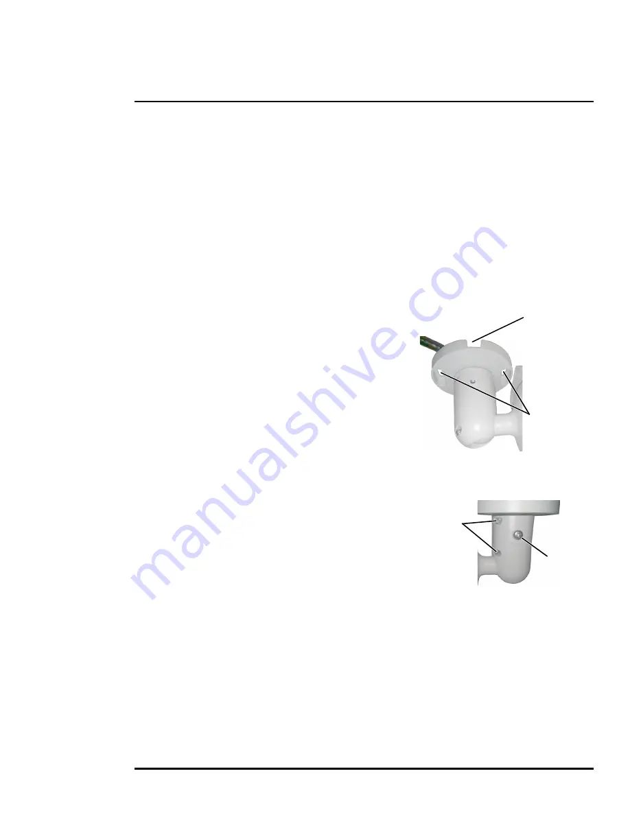
3. Drill the cable entry hole for cables or use the slot for
surface mounting the cables.
4. Drill holes slightly smaller than the supplied plastic screw
anchor on each marked screw hole.
5. Insert the plastic screw anchors into the drilled holes.
6. Connect the camera cables and thread them through the
cable entry hole. Refer to
Camera Connections, pg. 9
for cable connections.
7. Match the mounting slots of the camera with the plastic screw anchors at the installation location.
8. Fasten the camera with the supplied M4 screws.
9. Loosen the set screws in order to manipulate the
camera positioning at the ball joint. The camera can be
rotated, twisted, and pointed up or down at the ball joint.
10. Point the camera in the desired direction and fasten the
screws.
M4 mounting
slots
Slot for surface
mounting
cable
Ball-joint
set screws
Base
set screw


