FLIR
IM75
USER
GUIDE
Document
Identifier:
IM75
‐
en
‐
US_AA
9
1
2
4
3
1
1
2
3
4
5
6
8
7
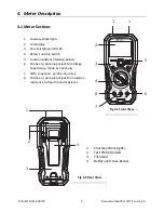
4.
Meter
Description
4.1
Meter
Sections
1.
Courtesy
Work
lights
2.
LCD
Display
3.
Pass
‐
Fail
(green/red)
LED
4.
Rotary
Function
Switch
5.
Function
Buttons
(detailed
below)
6.
Positive
(+)
probe
input
jack
for
Voltage,
Capacitance,
Diode,
&
Continuity
7.
COM
(
negative
‐
)
probe
input
jack
8.
Positive
(+)
probe
input
jack
for
insulation
resistance
and
earth
bond
resistance
1.
Courtesy
Work
Lights
2.
Test
Probe
Holders
3.
Tilt
Stand
4.
Battery
and
Fuse
Access
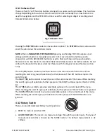
Fig
4
‐
1
Front
View
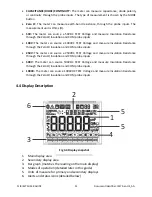
Fig
4
‐
2
Rear
View

