Installing M-Series Camera Systems
432-0003-60-12 Version 100
May 2017
10
Multiple JCU/Camera Installations
In some installations, the system may include additional components, such as additional cameras
or JCUs, video equipment, or network equipment. More than one JCU can be used to control the
camera, and more than one display can be used to view the video. Also a single JCU can be used
to control more than one camera and optionally you can also use a PC to control the camera.
Refer also to the M-Series ICD (FLIR Doc. # 432-0003-XX-YY) for interconnect diagrams showing
several possible system configurations using more than one JCU.
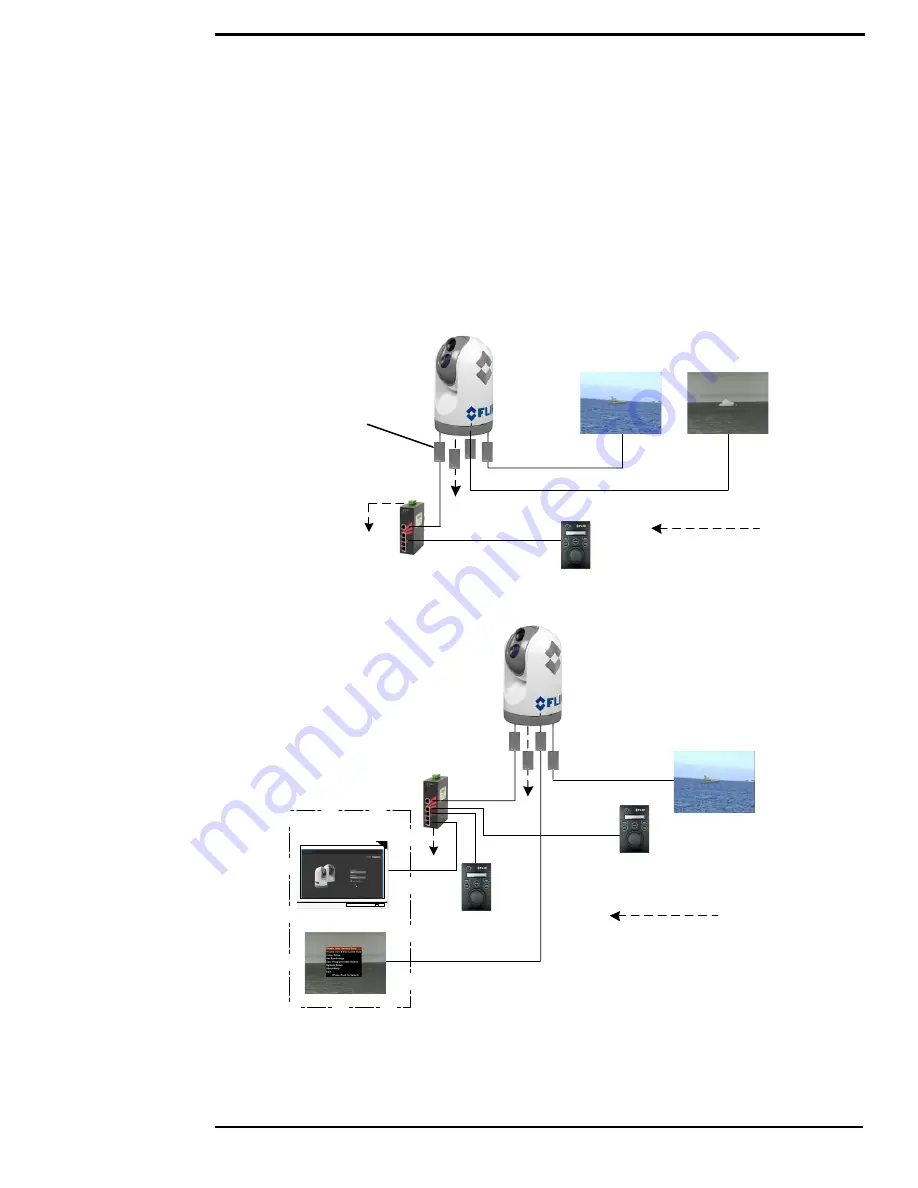
The following diagrams show dual-payload system configurations using a customer supplied PoE
switch and a separate monitor for each video signal.
Dashed lines represent
connection to power
Ethernet
Video VIS/IR
JCU
Customer supplied monitors
PoE switch
Noise suppression
ferrites (4)
Video IR
Figure 1-1: Basic installation using a customer PoE switch
Configuration Control
Ethernet
JCU
Dashed lines represent
connection to power
PC
Video VIS/IR
Video IR
JCU
Customer supplied monitor
PoE Switch
Customer supplied
Figure 1-2: Two station installation with a PC


