FLIR
MR160
USER
GUIDE
Document
Identifier:
MR160
‐
en
‐
US_AA
12
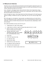
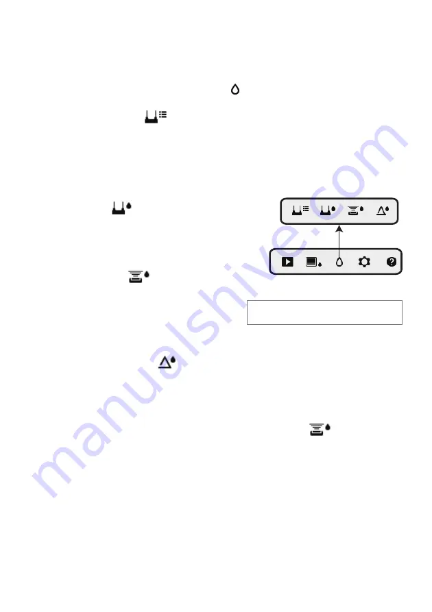
5.2.4
MOISTURE
Mode
From
the
Main
Menu
select
the
MOISTURE
mode
icon
(1).
Refer
to
Fig.
5
‐
4.
Then
choose
from
the
four
Moisture
mode
options
(items
2,
3,
4,
and
5)
as
described
below.
1. Moisture
Mode
Icon
from
the
Main
Menu
2.
MATERIAL
GROUPS
Select
a
material
wood
group
that
best
matches
the
material
under
test.
This
applies
only
for
external
pin
‐
based
probe
use;
Use
the
navigation
buttons
to
scroll
through
the
group
list
and
use
the
Select
button
to
choose
the
group.
The
selected
group
will
show
a
blue
dot.
See
the
Material
Wood
Group
List
Appendix
in
Section
9.
3.
PIN
MODE
PIN
mode
must
be
selected
when
the
external
pin
‐
based
probe
is
used.
Note
the
pin
icon
(3)
on
the
upper
left
of
the
main
display
when
selected.
4.
PINLESS
MODE
PINLESS
mode
must
be
selected
when
using
the
internal
sensor.
Note
the
pinless
icon
(4)
on
the
upper
left
of
the
main
display
when
selected.
5. SET
REFERENCE
MODE
SET
REFERENCE
is
used
to
compare
the
displayed
readings
against
a
stored
reference
measurement
(see
Section
5.2.7
Set
Reference
Mode
).
This
mode
applies
only
to
readings
taken
with
the
pinless
internal
sensor.
5.2.5
Internal
Moisture
Sensor
Measurements
(Pinless)
1. Follow
the
steps
in
Section
5.2.1
through
5.2.4
and
select
the
Pinless
mode.
2. Place
the
internal
moisture
sensor
(back)
on
the
surface
of
the
material
to
be
tested.
Apply
light
pressure
to
ensure
that
the
internal
sensor
is
completely
flat
against
the
surface
of
the
material
under
test.
3. The
relative
moisture
reading
is
displayed
on
the
main
display
in
the
upper
left
hand
corner
(IR
+
Moisture
mode)
or
as
bargraph
with
accompanying
digits
(Moisture
‐
only
mode).
Refer
to
example
screens
shown
in
Fig.
5
‐
1
and
Fig.
5
‐
2.
4. For
best
results,
keep
hands,
surfaces,
and
objects
away
from
the
rear
internal
moisture
sensor
area
when
taking
measurements.
Fig.
5
‐
4
Moisture
mode
icons
1
2
3
4
5


