PTZ-35x140
User’s Guide 427-0011-00-10 Version 100
QUICK-START INFORMATION
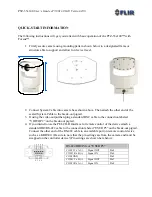
The following instructions will get you started with basic operation of the PTZ-35x140™ with
Foveus™.
1.
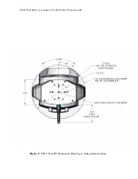
Firmly secure camera using mounting pattern shown below to a designated frame or
structure able to support and allow for device travel.
2.
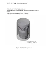
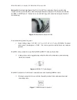
Connect System Cable into camera base shown above. Then attach the other end of the
sealed System Cable to the break-out pigtail.
3.
If using the video output then plug a standard BNC cable to the connection labeled
“VIDEO P2” on the break-out pigtail.
4.
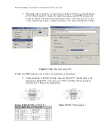
If you intend to use the PELCO-D Interface for remote control of the device attach a
standard DB9 RS-422 cable to the connection labeled “USER P3” on the break-out pigtail.
Connect the other end of the RS-422 cable to an available port on remote control device
such as a KBD300. (Be sure to note that the pin settings are from the camera and must be
swapped on the controller device!) Pin settings are shown here below:
RS-422 DB9 Pin or “USER P3”
COM 1 Tx A (-)
Signal OUT
Pin 2
COM 1 Rx B (+)
Signal IN
Pin 3
COM GND
Pin 5
COM 1 Tx B (+)
Signal OUT
Pin 7
COM 1 Rx A (-)
Signal IN
Pin 8


