


nual –
Benutzerhandbuch
–
Manual del usuario
–
Manuel de l’utilisateur
– Manuale dell’utente –
Manual do utilizador
– Felhasználói kézikönyv – Käyttäjän opas –
Betjenings-
dning
– Brukerveiledning – Instrukcja obsługi –
Bruksanvisning
– Kullanım Kılavuzu – Uživatelská příručka –
Gebruikershandleiding
User’s manual –
Benutzerhandbuch
–
Manual del usuario
–
Manuel de l’utilisateur
– Manuale dell’utente –
Manual do utilizador
– Felhas-
ználói kézikönyv – Käyttäjän opas –
Betjeningsvejledning
– Brukerveiledning – Instrukcja obsługi –
Bruksanvisning
– Kullanım
Kılavuzu – Uživatelská příručka –
Gebruikershandleiding
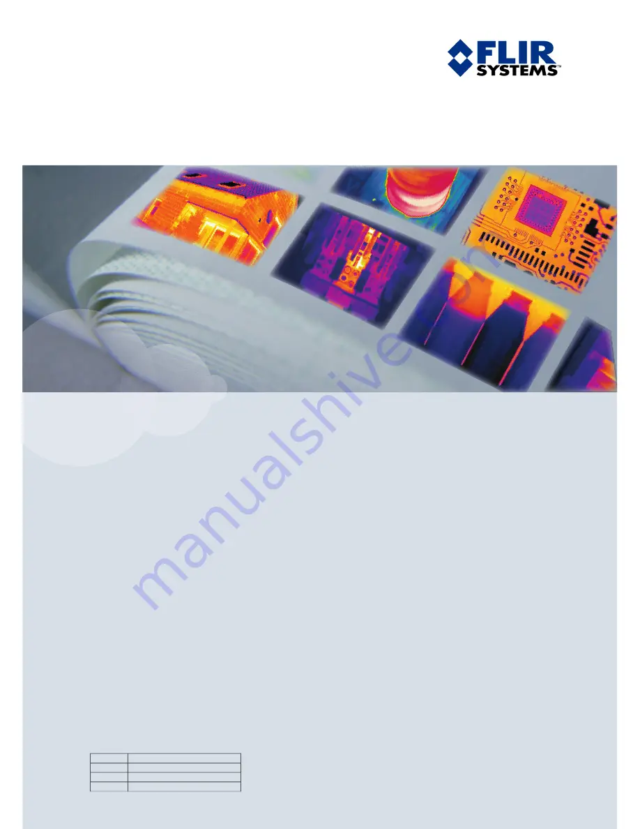
ThermaCAM™ B2
User’s manual
1557882
Publ. No.
a156
Revision
English (EN)
Language
February 28, 2006
Issue date
Summary of Contents for ThermaCAM B2
Page 2: ......
Page 4: ......
Page 6: ......
Page 7: ...ThermaCAM B2 User s manual Publ No 1557882 Rev a156 ENGLISH EN February 28 2006...
Page 191: ......


