10714003;a3
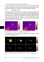
Figure 7.14 Examples of infrared images of load variations
The image to the left shows three cables next to each other. They are so far apart that
they can be regarded as thermally insulated from each other. The one in the middle
is colder than the others. Unless two phases are faulty and overheated, this is a typical
example of a very unsymmetrical load. The temperature spreads evenly along the
cables, which indicates a load-dependent temperature increase rather than a faulty
connection.
The image to the right shows two bundles with very different loads. In fact, the bundle
to the right carries next to no load. Those which carry a considerable current load,
are about 5°C (9°F) hotter than those which do not. No fault to be reported in these
examples.
7.5.5
Varying cooling conditions
10714103;a3
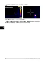
Figure 7.15 An infrared image of bundled cables
When, for example, a number of cables are bundled together it can happen that the
resulting poor cooling of the cables in the middle can lead to them reaching very high
temperatures. See the image above.
The cables to the right in the image do not show any overheating close to the bolts.
In the vertical part of the bundle, however, the cables are held together very tightly,
the cooling of the cables is poor, the convection can not take the heat away, and the
cables are notably hotter, actually about 5°C (9°F) above the temperature of the better
cooled part of the cables.
7
32
Publ. No. 1557966 Rev. a155 – ENGLISH (EN) – February 6, 2006
7 – Introduction to thermographic inspections of electrical installations
Summary of Contents for ThermaCAM P45
Page 2: ......
Page 4: ......
Page 6: ......
Page 7: ...ThermaCAM P45 User s manual Publ No 1557966 Rev a155 ENGLISH EN February 6 2006...
Page 16: ...xvi Publ No 1557966 Rev a155 ENGLISH EN February 6 2006...
Page 214: ...198 Publ No 1557966 Rev a155 ENGLISH EN February 6 2006...
Page 215: ......


