These steps are provided to provide a simple overview. Please read the entire
User Manual before putting these devices into professional operation.
CAUTION
The VS290–32 and VS290-33 are suitable for use in CAT IV 600 V AC environments. The
VS290-21 is not intended for use in high voltage (> 600 V AC) environments.
NOTE
Please update the VS290–00 Videoscope Display’s firmware, as explained in Section 14, be-
fore first use and periodically thereafter, to ensure optimum performance.
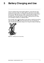
1. Insert a fully charged battery into the VS290–00 handle.
2. If the probe is purchased separately from the Videoscope Display, please
connect the probe to the Videoscope Display before proceeding. Ensure
that the VS290–00 is powered off before attaching or removing a probe.
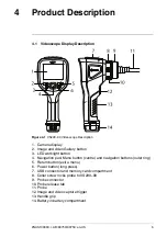
Note that the release tab (item no. 10 in Figure 4.1) must be pushed to re-
lease a probe from the Videoscope display when removing it.
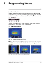
3. Long press the power button
to power up.
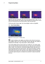
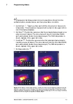
4. When powered, the VS290–00 displays a camera image and several func-
tion indicators, dependant on the configuration of the instrument.
Figure 6.1
Viewing a camera image.
#NAS100060; r. AB/80750/80750; en-US
13
Summary of Contents for VS290-00
Page 1: ...USER MANUAL Thermal Videoscope Kits Kit nos VS290 2x and VS290 3x...
Page 2: ......
Page 3: ...USER MANUAL Thermal Videoscope Kits NAS100060 r AB 80750 80750 en US iii...
Page 4: ......
Page 49: ......

