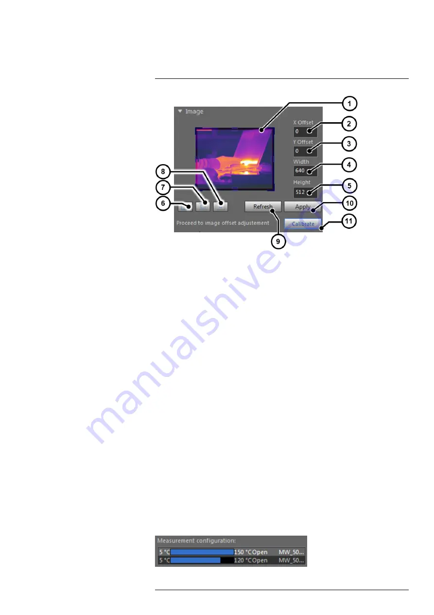
Figure 6.2
Image size adjustment
1. Preview window. The window size can be selected by dragging the handles. The en-
tire box can be dragged to set the location.
2. The
X
offset can be manually set in this field.
3. The
Y
offset can be manually set in this field.
4. The window width can be manually set in this field.
5. The window height can be manually set in this field.
6. Set the window size to full detector size (640 × 512).
7. Set the window size to half detector size (320 × 256 centered).
8. Set the window size to quarter detector size (160 × 128 centered).
9. Refresh the preview window with the last acquired image from the camera.
10. Apply the settings to the camera.
11. If needed, calibrate the image against a homogeneous reference target (also called
“1 point NUC”).
6.4.4
Measurement configuration
6.4.4.1
General
A measurement configuration is a combination of optical setup (lens and spectral filter),
integration mode setting, and Camera Link setting.
The measurement configurations available in the camera are displayed in the FLIR Re-
searchIR Max interface. Each configuration is described with minimum and maximum
calibrated temperatures, the lens and filter type, the integration mode (ITR or IWR), and
the Camera Link setting (Base/Medium).
For lenses with automatic identification (see section 6.3.2.3
the camera automatically selects the measurement configuration corresponding to the
lens.
You can also select the measurement configuration manually. Take care to select the
measurement configuration corresponding to the lens, filter, integration mode setting
(ITR or IWR), and the Camera Link setting (Base or Medium) in use. The configuration is
selected by clicking on it. It is then highlighted in light gray. Once selected, the camera is
automatically set to this configuration.
#T810207; r. AA/43061/43086; en-US
22
Summary of Contents for X6520sc Series
Page 1: ...User s manual FLIR X6520sc series ...
Page 2: ......
Page 3: ...User s manual FLIR X6520sc series T810207 r AA 43061 43086 en US iii ...
Page 4: ......
Page 8: ......
Page 64: ...Mechanical drawings 10 See next page T810207 r AA 43061 43086 en US 56 ...
Page 111: ......


